


Appendix A: Technical Specifications
50
Quality and Reliability: MTBF (calculated with Telcordia
standards) 270,000 hours
Connectors and Port Pinouts
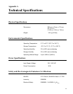
This section lists the connectors and connector pinouts for the
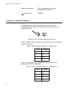
AT-GS950/8 switch. Figure 23 illustrates the pin layout for an RJ-45
connector and port.
Figure 23. RJ-45 Connector and Port Pin Layout
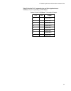
Table 6 lists the RJ-45 pin signals when a twisted pair port is operating in
the MDI configuration.
Table 7 lists the RJ-45 port pin signals when a twisted pair port is
operating in the MDI-X configuration.
Laser Safety EN60825
Table 6. MDI Pin Signals (10Base-T or 100Base-TX)
Pin Signal
1TX+
2TX-
3RX+
6RX-
Table 7. MDI-X Pin Signals (10Base-T or 100Base-TX)
Pin Signal
1RX+
2RX-
3TX+
6TX-
8
8
1
1