


AT-2911GP Gigabit Fiber Ethernet PoE+ Adapters Installation and User’s Guide
76
Overview
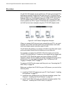
The AT-2911GP adapter card is installed on a PC and connects the PC to
the Ethernet network through the fiber optic port and a Powered Device
(PD) through the PoE+ copper port. A PD is a device powered through an
Ethernet cable by a Power Supply Equipment (PSE). A PC with the AT-
2911GP adapter card is a PSE; a VoIP phone, Wi-Fi access point, and
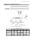
security camera are PD’s. Figure 54 illustrates the configuration of PC’s
and VoIP phones as an example using the AT-2911GP adapter cards.
.
Figure 54. VoIP Phone Configuration Example
When you connect VoIP phones to your network through PC’s, you must
separate voice traffic from data traffic using VLAN because voice traffic
must have higher priority over other types of traffic.
The AT-MUX utility allows you to assign a VLAN ID to the fiber and copper
ports and bridges frames from the copper port to the fiber port.
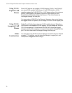
For example, you assign the VLAN ID 150 to the copper port and the
VLAN ID 10 to the fiber port. Frames from the copper port are tagged with
the VLAN ID 150. When the copper port does not have a VLAN ID
assigned, frames from the copper port remain untagged when they arrive
at the switch. For more tagging examples, See “Configuring VLAN
Tagging on Adapter Ports” on page 77.
To assign a VLAN ID to the copper and fiber ports, see “Accessing the AT-
MUX Utility” on page 69.
Before you configure the AT-MUX for your VoIP phones, you must do the
following tasks:
Install the AT-2911GP adapter onto your PC. See Chapter 2, “Installing
the Hardware” on page 23.
Install the driver software onto your Windows operating system. See
Chapter 3, “Installing the Driver Software” on page 35.
Install The AT-MUX utility onto your Windows operating system. See
Chapter 4, “Installing the AT-MUX Utility” on page 63.