


Installation & Safety Guide 7
Procedure
1. If you have any optional expansion modules, install them first.
The AT-8600 Series switches support the AT-A45/xx, AT-A46, AT-A47, and
AT-A65 expansion modules. Install them by following the instructions in the
relevant guide:
• AT-A65 Expansion Module Installation and Safety Guide for the AT-A65
module only.
• AT-A45/xx Series, AT-A46, and AT-A47 Expansion Modules Installation Guide
for the other expansion modules.
These instructions ship with individual expansion modules, and are also
available from www.alliedtelesis.com/support/software.
Note that if you insert or remove a module when the switch is already
powered on, you must restart the switch before you can use the module.
2. Place the switch in its operating location.
If installing the switch in a rack:
• Remove the rubber feet on the bottom of the switch with a flat-head
screwdriver.
• Attach the two rack-mounting brackets to the switch with the screws
provided in the rack-mount kit.
3. Mount the switch in the rack using rack-mount screws
Note that the screws are not provided with the switch.
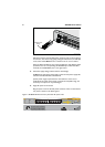
4. Install any SFPs.
You can install optional SFP (Small Form-factor Pluggable) modules into the
AT-8648T/2SP.
Warning Do not look into the optical ports of SFP cables or transceivers.
Invisible laser radiation may be emitted from disconnected fibres or
connectors.
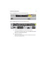
In both SFP ports, the SFP transceivers must be inserted with the release
lever hinge at the bottom. Use the following figure as a guide.