


8 AT-8600 Series Switch
.
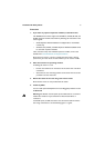
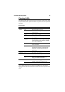
Slide the transceiver into the SFP socket, and firmly press it until it engages.
To remove it, first release it by gently pulling the release lever, and then pull
it out of the socket. Never force a transceiver into or out of a socket.
When an SFP is installed into one of the two SFP ports, that SFP port takes
precedence over its corresponding 10/100/1000T port. When the SFP is
removed, the 10/100/1000T port is once again active.
5. Check the supply voltage and the switch’s rated voltage
AT-8600 Series switches are fitted with a universal main power supply that
functions from100–240
VAC and 50–60 Hz.
Specific power supply requirements for the model are on the rear or
underside of the switch. If the supply is outside the acceptable range, the
switch may not operate or may be damaged.
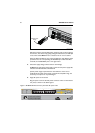
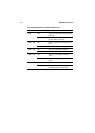
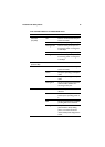
6. Apply AC power to the switch.
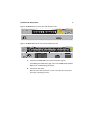
Plug the power cord into the AC power connector. This is on the switch’s
rear panel, as shown in the below figures.
Figure 1: AT-8624T/2M front and rear panel with AC power inlet
AT-8600_sfp_shaded
release lever
hinge
1 3 5 7 9 11 13 15 17 19 21 23
24681012141618202224
LINK
MODE
LINK
MODE
FAULT
RPS
MASTER
PWR
1357911
2 4 6 8 10 12
13 15 17 19 21 23
14 16 18 20 22 24
26
COL
100
FULL
ACT
AT-8624T/2M
Layer 3 Fast Ethernet Switch
MODE
RS-232
TERMINAL PORT
STATUS
25