


6 AT-8600 Series Switch
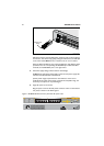
Installing the Switch
Ports on the switch are suitable only for connections within buildings (intra-
building) and with cables unexposed to the outside.
Before you begin
■ Read the safety information.
For your well-being and that of the equipment, read the safety information in
this document. You can also download this document from the
Documentation and Tools CD-ROM or from
www.alliedtelesis.com/support/
software.
■ Verify the package contents if you have not already done so.
See “Package Contents” on page 4. If any items are damaged or missing,
contact your authorised distributor or reseller.
■ Gather necessary tools and equipment:
• Phillips # 2 screwdriver to loosen the blanking plate, if any
• 4 sets of rack-mount screws and nuts, and a suitable screwdriver
To install a DC version of the PSU, you need an appropriate DC power
source, DC supply cable, ring connectors, and a crimp tool.
■ Choose a suitable operating location.
You can install the switch either in a 19-inch rack, on a flat bench, or against
a wall. Follow the guidelines in
“Selecting a Site” on page 5 to choose a
location.
■ To ensure rack-mounted installations are earthed for compatibility with
Network Equipment Building System (NEBS), do the following:
• Remove non-conductive coatings, such as lacquer and enamel, from the
rack rail where hardware will contact it. Also remove coatings from
unplated connectors, braided strap, and bus bars, and bring them to a
bright finish. Then coat them with an antioxidant before connecting
them. During installation, thread-forming screws with star washers may
be used for this purpose
• All bare conductors must be coated with an appropriate antioxidant
compound before making crimp connections.
Warning Both AC and DC versions of this equipment must be earthed through
the power cables provided.