


Installation and Safety Guide
9
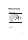
The adjustable bracket extensions are rotationally symmetrical when
attached to the rear brackets. When viewed from the rear of the switch,
the flanges on the bracket extensions are at the bottom on the right and at
the top on the left. This allows adequate clearance when a power supply
unit or fan-only module is removed from the switch.
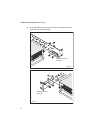
9. Attach the adjustable bracket extensions to the rack using rack mounting
screws.
10. Tighten the nuts that secure the adjustable bracket extensions to the rear
brackets.
11. Check that all screws and nuts are fully tightened.
Applying Power to the Switch
The switch has two bays in the rear. Your switch comes with one pre-installed
power supply unit (PSU). Depending on the model, the switch also has one
fan-only module (FOM) or one blanking panel over a power supply bay,
AC power supply
Important information for service personnel:
■ CAUTION: double pole/neutral fusing
■ the rating of fuses FH101 and FH102 is 250 V, 5 A (AT-PWR01 only)
Procedure for AC power supply
To apply power to the PSU, plug the AC power cord that is provided into the
power inlet on the faceplate of the PSU. Then connect the power cord to the
main power supply.
DC supply cable and power supply
Supply cable specifications
■ three-core cable is required
■ minimum core size: 3.3 mm
2
(12 AWG) high strand count copper wire
■ minimum cable rating: 600 V, 90 degrees C
Power supply specifications
■ 40 to 60 V, 48 V nominal
■ supports either positive grounded or negative grounded operation
■ a 15 Amp certified/listed circuit breaker is required for circuit protection