


Hardware Reference 11
C613-03022-00 REV K
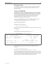
If you are unsure of whether to terminate the line or not, contact your ISDN
service provider or your authorised Allied Telesis distributor or reseller.
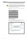
Warning
Do not attempt to change any jumpers on the NSM while the switch or
router is connected to a power supply or a live network. Disconnect the mains
power supply, any redundant power supply, and any cable attached to the ISDN
ports of the NSM. Dangerous voltages may be present on some parts of the NSM
board, even if the switch or router is powered off.
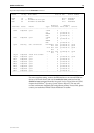
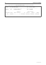
The BRI interfaces use RJ-45 connectors. Table 3 shows the pinout of the BRI
interfaces.
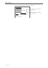
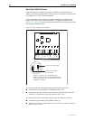
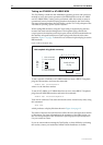
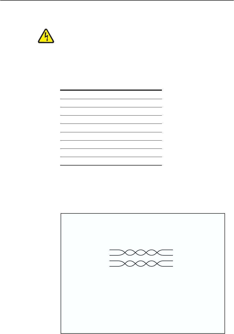
ISDN S/T Interface Cables
Figure 6 on page 11 shows how to wire a cable to connect a Basic Rate Interface
(BRI) to the ISDN network terminating equipment (NT).
Figure 6: Pin wiring diagram for an ISDN Basic Rate straight-through Interface cable
Table 3: Pinout of the Basic Rate ISDN S/T interfaces
Pin S/T Interface Functions
1-
2-
3TX+
4RX+
5RX-
6TX-
7-
8-
RJ45
(to NT)
1
2
3
6
5
4
7
8
→
→
←
←
Not connected
Not connected
RX+
RX-
TX-
TX+
Not connected
Not connected
Notes:
(1) → Output from switch or router; ← Input to switch or router.
(2) Use twisted pair cable, with pairs 3 and 6, and 4 and 5.
(3) Each wire is connected to the same pins at each end.
(4) Cable version 1.0.
1
2
3
6
5
4
7
8
Not connected
Not connected
TX+
TX-
RX-
RX+
Not connected
Not connected
→
→
←
←
BRI1NT
RJ45
(to switch or router)