


Installation Guide
13
Checking LEDs
LEDs on PSUs, fans, and the front panels of switches indicate the operational
status of the devices. After you have installed a PSU or fan and have powered on
the switch, check the LEDs to verify operation by using the following tables.
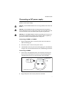
PWR01
PWR02
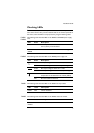
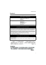
The following table describes LEDs on the PWR01 and PWR02 power supply
units.
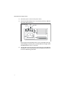
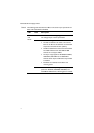
PWR05 The following table describes LEDs on the PWR05 power supply unit.
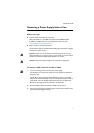
FAN01 The following table describes LEDs on the FAN01 fan-only module.
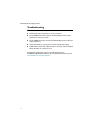
FAN03 The following table describes LEDs on the FAN03 chassis fan module.
LED State Description
FAULT Red The temperature on the PSU has exceeded the limit of
75º C (167º F), or the fan failed.
PWR
GOOD
Green A PSU is installed in the switch and is delivering power.
LED State Description
~
Green AC input voltage is within 90-264VAC, 47-63Hz.
Off AC input voltage is outside the acceptable range.
Green DC output voltage is within 12V +/- 10%.
Off DC output voltage is outside the acceptable range.
Red A fault has occurred. There is either a fan failure, or the
temperature has exceeded its limit of 70ºC (158ºF).
Off No fault conditions detected.
LED State Description
FAULT Red The fan has failed.
LED State Description
FAN
STATUS
Red The fan has failed.