


AT-iMG646xx Series Intelligent Multiservice Gateway and AT-EN646 Enclosure Installation Guide
Section I: Outdoor Installation 61
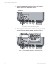
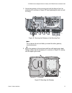
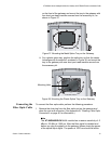
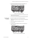
on the front of the gateway and mount the tray to the gateway with
four short pan head machine screws from the accessory kit, as
shown in Figure 37.
Figure 37. Mounting the Metal Splice Tray on the Gateway
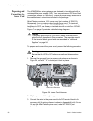
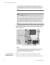
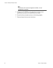
For a plastic splice tray, position the splice tray so that the center
hole aligns with the standoff, as shown in Figure 38, and mount the
tray to the gateway with one short pan head machine screw from
the accessory kit.
Figure 38. Mounting the Plastic Splice Tray on the Gateway
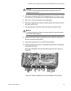
Connecting the
Fiber Optic Cable
To connect the fiber optic cable, perform the following procedure:
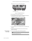
1. Remove the dust plug from the fiber optic port on the gateway and
clean the port and connector. (See Appendix B, “Cleaning Fiber Optic
Connectors” on page 91 for information.)
Note
The AT-iMG646BD-ON WAN module has a receive sensitivity of -3
dBm to -32 dBm at 1550 nm. After the fiber pigtail is installed and
before you plug the pigtail into the gateway, please check the power
of the optical input signal. The power at 1550 nm should fall within
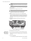
Mounting Hole