


AT-iMG646xx Series Intelligent Multiservice Gateway and AT-EN646 Enclosure Installation Guide
Section I: Outdoor Installation 63
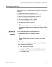
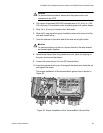
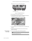
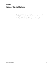
Figure 40, cut a 1/4” “X” in it, and put it back in place.
Figure 40. Telephone Wire Entrance
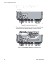
2. Slip the telephone wire through the grommet.
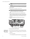
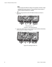
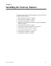
3. Connect the telephone wires to each pair of telephone terminal posts
in the enclosure, as shown in Figure 41, at 5.3 in-lbs.
Figure 41. Connecting the Telephone Wires
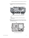
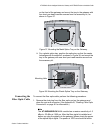
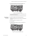
4. Secure the telephone wire to the entrance with a UV-rated wire tie (not
provided).
5. Seal the grommet with electrical tape (not provided) and silicone
sealant (not provided).
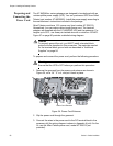
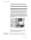
Connecting the
LAN Cables
To connect the LAN cables, perform the following procedure:
Note
Allied Telesis recommends that you fully wire all six ports to allow for
easy service expansion in the future.
859
Telephone Wire Entrance