


Appendix A: MSTP Overview
364
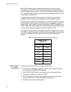
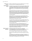
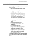
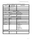
Figure 143. CIST and VLAN Guideline - Example 2
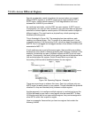
When port 3 on switch B receives a BPDU, the switch notes the port sending
the packet belongs only to CIST 0. Therefore, switch B uses
CIST 0 in determining whether a loop exists. The result would be that the
switch detects a loop because the other port is also receiving BPDU packets
from CIST 0. Switch B would block port 3 to cancel the loop.
To avoid this issue, always assign all VLANs on a switch, including the Default
VLAN, to an MSTI. This guarantees that all ports on the switch have an MSTI
ID and helps to ensure that loop detection is based on MSTI, not CIST.
1357
911
1315
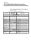
AT-GS950/16PS
Gigabit Ethernet PoE+ Switch
plus
1357
911
1315R
246810121416R 1516
1357
2468
9 11 13 15R
10 12 14 16R
15 16
100 LINK ACT
1000 LINK
SFP
ACT
CLASS 1
LASER PRODUCT
SFP
PD ERRPD ON
ACT1000 LINK
ACT10/100 LINK
PORT ACTIVITY
POE MAX
SYSTEM
POE
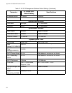
1357
911
1315
AT-GS950/16PS
Gigabit Ethernet PoE+ Switch
plus
1357
911
1315R
246810121416R 1516
1357
2468
9 11 13 15R
10 12 14 16R
15 16
100 LINK ACT
1000 LINK
SFP
ACT
CLASS 1
LASER PRODUCT
SFP
PD ERRPD ON
ACT1000 LINK
ACT10/100 LINK
PORT ACTIVITY
POE MAX
SYSTEM
POE
2719
Port 1 (Default VLAN)
Switch A
Switch B
Instances: CIST 0 and MSTI 15
Port 6 Port 8
(VLAN 3)
BPDU Packet
Instances: CIST 0
Port 3 (Blocked)
BPDU Packet