


Chapter 7: Powering On the Chassis
180
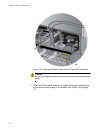
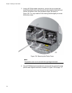
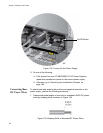
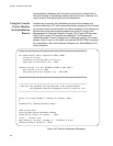
Figure 138. Turning On the Power Supply
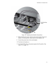
11. Do one of the following:
If the chassis has two AT-SBxPWRSYS1 DC Power Supplies,
repeat this procedure to power on the second power supply.
Otherwise, go to “Monitoring the Initialization Process” on
page 184.
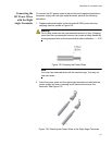
Connecting Bare
DC Power Wires
To attach bare lead wires to the positive and negative terminals on the
power supply, perform the following procedure:
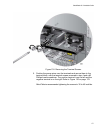
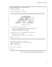
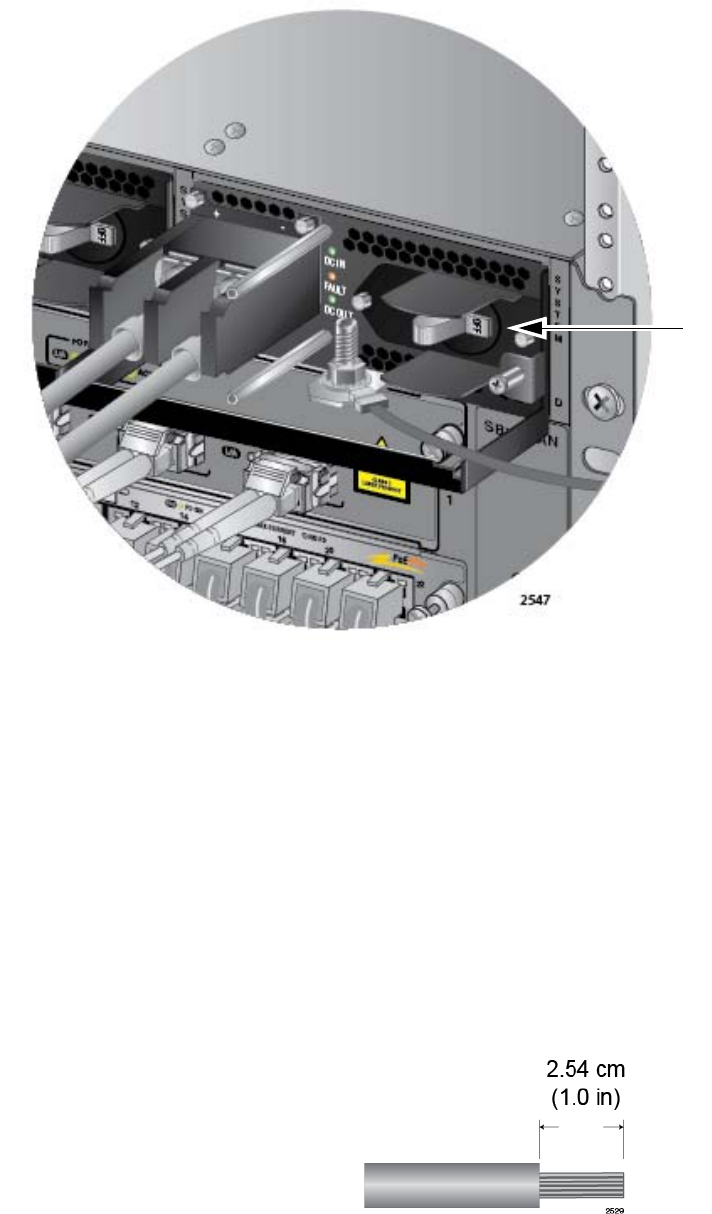
1. Prepare adequate lengths of two solid or stranded 8 AWG DC power
wires by stripping them as shown in Figure 139.
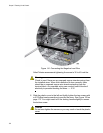
Figure 139. Stripping Solid or Stranded DC Power Wires
On/Off Switch