


SwitchBlade x3112 Installation Guide
161
Powering On the AT-SBxPWRSYS1 DC System Power Supply
This section contains instructions on how to power on the AT-
SBxPWRSYS1 DC Power Supply. For installation instructions, refer to
“Installing the AT-SBxPWRSYS1 DC Power Supply” on page 107.
The power supply unit has a ground connection and positive and negative
DC terminals. You may install the ground and power lead wires using the
terminal lugs that come with the unit. You may also use bare wire
installation. The wire requirements are slightly different for terminal
installation versus bare wire installation. Here are the wire requirements if
you are using the terminals that come with the power supply:
Two 8 AWG stranded power wires (not provided)
One 10 AWG stranded grounding wire (not provided)
Here are the wire requirements for bare wire installation:
Two 8 AWG solid or stranded power wires (not provided)
One 10 AWG solid or stranded grounding wire (not provided)
Here is a list of the required tools:
Crimping tool (not provided)
8 mm wrench (not provided)
#1, #2, and #3 Phillips-head screwdrivers (not provided)
#3 Phillips-head 30 to 40 inch-lbs Phillips-head torque screwdriver
(optional - not provided)
Here are the procedures for powering on the AT-SBxPWRSYS1 DC
Power Supply:
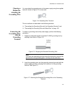
“Choosing a Method for Attaching the Grounding Wire” on page 163
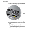
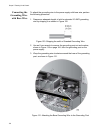
“Connecting the Grounding Wire with the Grounding Terminal” on
page 163
“Connecting the Grounding Wire with Bare Wire” on page 166
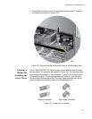
“Choosing a Method for Attaching the Power Wires” on page 167
“Connecting the DC Power Wires with the Straight Terminals” on
page 168
“Connecting the DC Power Wires with the Right Angle Terminals” on
page 175
“Connecting Bare DC Power Wires” on page 180
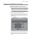
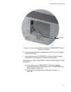
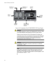
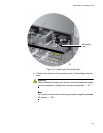
The components of the power supply are identified in Figure 114 on page
162.