


Chapter 7: Powering On the Chassis
182
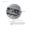
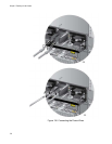
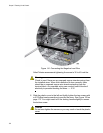
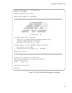
Figure 141. Connecting the Negative Lead Wire
Allied Telesis recommends tightening the screw to 30 to 40 inch-lbs.
Warning
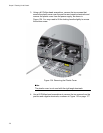
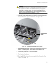
Check to see if there are any exposed copper strands coming from
the installed wires. When this installation is done correctly there
should be no exposed copper wire strands extending from the
terminal block. Any exposed wiring can conduct harmful levels of
electricity to persons touching the wires. E12
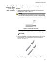
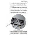
6. Slide the plastic cover to the left and lightly tighten the two screws with
a #1 Phillips-head screwdriver to secure the cover. See Figure 129 on
page 172. You might need to lift the locking handle slightly to access
the bottom screw.
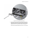
Caution
Do not over tighten the screws or you may crack or break the plastic
cover.