


AT-x210-9GT, AT-x210-16GT, and AT-x210-24GT Switches Installation Guide
27
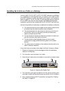
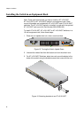
Installing the Switch on a Table or a Desktop
You can install AT-x210-16GT and AT-x210-24GT switches on a desktop,
or in a standard 19-inch equipment rack. To install AT-x210-16GT and AT-
x210-24GT switches in a rack, see “Installing the Switch in an Equipment
Rack” on page 28. The AT-x210-9GT is rack mountable using an optional
AT-x210-9GT rack mount kit (Part Number: 990-003904-00).Separate
installation instructions are included with the AT-x210-9GT rack mount kit.
Here are the guidelines to selecting a suitable site for desktop or table use:
The table should be level and stable and the power outlets should
be located near the switches and be easily accessible.
The site should allow for easy access to the ports on the front of
the switches, so that you can easily connect and disconnect
cables, and view the port LEDs.
The site should not expose the switches to moisture or water and
the site should be a dust-free environment.
The site should include dedicated power circuits or power
conditioners to supply reliable electrical power to the network
devices.
The rubber feet on the bottom of the switches should be left on for
table or desktop installation.
If you switch does not already have rubber feet fitted, fit these as follows:
1. Remove all equipment from the package and store the packaging
material in a safe place.
2. Turn the switch over and place it on a table.
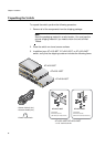
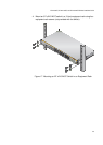
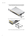
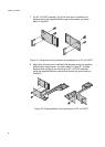
3. Screw the four rubber feet to the bottom of the switch as shown below:
Figure 14. Attaching the Rubber Feet
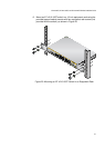
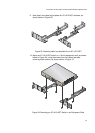
4. Turn the switch over again and place it on a flat, secure surface (such
as a desk or table) leaving ample space around the unit for ventilation.
5. Go to “Installing Optional SFP Transceivers” on page 35 or “Cabling
the Switch” on page 39.
1971