


10 Rapier Switch
Software Release 2.3.1
C613-04017-01 REV D
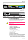
System LEDs and What They Mean
System LEDs on its front panel indicate the switch’s operational status.
1. DC models of the Rapier Switch do not have an RPS connector and the RPS LED will not function.
2. Not included on the Rapier 48, G6, G6F-SX/SC, G6F-LX/SC, or G6F-SX/MT-RJ.
3. Hot swapping is supported by Software Release 2.3.1 or later. AT-AR021 (S) BRI-S/T, AT-AR021 (U)
BRI-U, AT-AR022 ETH, AT-AR023 SYN, and AT-AR026 4ETH PICs can be hot swapped.
The Rapier Switch Hardware Reference has further troubleshooting information,
including information on Switch Port and Uplink Module LEDs.
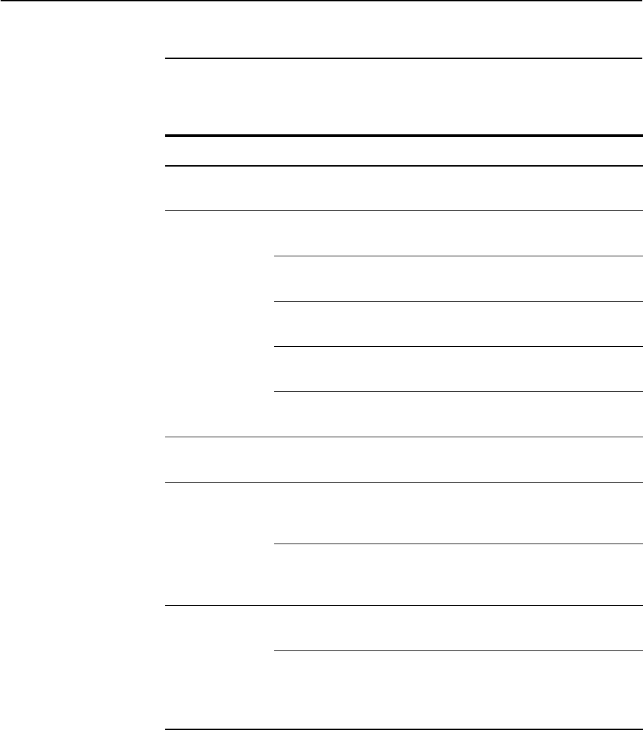
System LEDs
LED State Function
Power Green The switch is receiving power and the voltage
is within the acceptable range
Fault Red The switch or management software is
malfunctioning
1 flash A switch fan has failed. (The LEDs will not
indicate an RPS fan failure.)
3 flashes If an RPS is connected, the switch’s PSU (Power
Supply Unit) has failed
4 flashes If RPS monitoring is enabled, the RPS PSU has
failed
5 flashes If RPS monitoring is enabled, an RPS is not
connected or is not operational
RPS
1
(Redundant
Power Supply)
Green An RPS is connected to the switch
In use
2
(Rear panel)
Green An NSM is installed, is receiving power, and is
operational. The NSM and its PICs are not
ready to be hot swapped
Off No NSM is installed, or the NSM is not installed
correctly (the switch unit has not recognised
the NSM)
Swap
2
(Rear panel)
Green The NSM and its PICs are ready to be hot
swapped
Off The Hot Swap button must be pressed before
the NSM or PICs can be hot swapped, or the
software release does not support hot
swapping
3