


V-MATRIX
400-0387-003
7
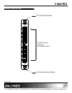
INSTALLING YOUR VM2382CF 6
Step 1. Turn off power to the V-Matrix enclosure.
Step 2. Remove a slot cover (VM2005BP) from
one of the unused slots of the enclosure
in order to install the VM2382CF.
Step 3. Slide the VM2382CF into the slot in the
enclosure in order to connect it to the bus.
Step 4. Make sure that the card fits into place and
then secure the card by tightening the
retainer screws located on the top and
bottom of the card.
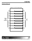
Step 5. Starting from the left, identify the slot
number of the VM2382CF in the
enclosure, and note that it will be used to
determine the output numbers for the
card.
Step 6. Restore power to the V-Matrix enclosure.
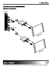
Step 7. Connect the Twisted Pair outputs of the
VM2382CF to the inputs of the TP
receiver using an adapter cable like the
MS8704TP.
Step 8. The VM2382CF is ready for operation.
Step 9. Each output card in the enclosure handles
8 output signals. In order to determine the
starting output number of the VM2382CF
just installed, multiply the slot number by
8 and subtract 7.
Example: The card is in slot 4.
(4 x 8) – 7 = 25
Therefore, the new card outputs are
numbered 25 through 32.
OPERATION 7
7.1 GENERAL OPERATION
The VM2382CF does not require any adjustments
for proper operation. Once installed, the
VM2382CF will operate trouble-free with no user
intervention.
TROUBLESHOOTING GUIDE 8
The VM2382CF unit supplied was carefully tested
and no problems were found. However, we would
like to offer the following suggestions:
8.1 NO DISPLAY
Cause 1: The cable connections are wrong.
Solution: Make sure the cables are properly
connected and that the inputs on the
VM2381CF are receiving the input
signals from the TP source. Next,
make sure the selected outputs on
the VM2382CF are connected to the
TP receiver and that the continuity
and wiring are good. If there is still
no display, see Cause 2.
Cause 2: The path is not properly selected.
Solution: Verify the signal is being properly
routed through the V-Matrix system.
NOTE: The ALTINEX Standard for
TP signals requires 4 Twisted Pairs.
All 4 pairs must be switched through
the V-Matrix system.
Example: The TP transmitter pairs
are being applied to inputs 1-4. If the
TP receiver is connected to the first
four outputs of the card in slot 1,
make the following connections:
Input 1 to Output 1
Input 2 to Output 2
Input 3 to Output 3
Input 4 to Output 4
If the TP receiver is connected to
first four inputs of the card in slot 2:
Input 1 to Output 9
Input 2 to Output 10
Input 3 to Output 11
Input 4 to Output 12
See RS-232 accessible commands
for the VM2210BE V-Matrix Basic
Enclosure User's Guide. If there is
still no display, see Cause 3.