


V-MATRIX
5
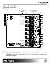
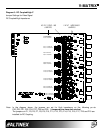
Diagram 2 : AC Coupled/75 Ohms
Jumper Settings for Video Signal
AC Coupled/75 Ohm Input Impedance
Note:
In the diagram above, the jumpers are set for 75 ohms input impedance on the following ports:
P20, P23, P21, P22, P24, P27, P25 and P26. (Jumpered pins have dark circles.)
The jumpers on P1, P5, P6, P7, P8, P9, P10, P11, P12, P13
, P14, P15, P16, P17, P18 and P19 are
removed for AC Coupling.
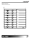
AC/DC COUPLING
JUMPERS JUMPERS
INPUT IMPEDANCE
75
HIZ
P20
P1,P5 OPEN-AC
P1,P5 CLOSE-DC
P23
HIZ75
P21
HIZ
75
P22
HIZ
75
P24
HIZ
75
P27
HIZ
75
P25
HIZ
75
P26
HIZ
75
P1,P5 OPEN-AC
P1,P5 CLOSE-DC
P10,P11 OPEN-AC
P10,P11 CLOSE-DC
P6,P7 OPEN-AC
P6,P7 CLOSE-DC
P8,P9 OPEN-AC
P8,P9 CLOSE-DC
P12,P13 OPEN-AC
P12,P13 CLOSE-DC
P18,P19 OPEN-AC
P18,P19 CLOSE-DC
P18,P19 OPEN-AC
P18,P19 CLOSE-DC
P18,P19 OPEN-AC
P18,P19 CLOSE-DC