


V-MATRIX
8
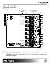
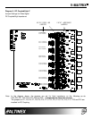
Diagram 5 : DC Coupled/High Z
Jumper Settings for Video Signal
DC Coupled/High Impedance
Note: In the diagram above, the jumpers are set for High impedance on the following po rts:
P20, P23, P21, P22, P24, P27, P25 and P26. (Jumpered pins have dark circles.)
The jumpers on P1, P5, P6, P7, P8, P9, P10, P11, P12, P13, P14, P15, P16, P17, P18 and P19 are
installed for DC Coupling.
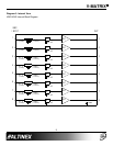
AC/DC COUPLING
JUMPERS JUMPERS
INPUT IMPEDANCE
75
HIZ
P20
P1,P5 OPEN-AC
P1,P5 CLOSE-DC
P23
HIZ75
P21
HIZ
75
P22
HIZ
75
P24
HIZ
75
P27
HIZ
75
P25
HIZ75
P26
HIZ
75
P1,P5 OPEN-AC
P1,P5 CLOSE-DC
P10,P11 OPEN-AC
P10,P11 CLOSE-DC
P6,P7 OPEN-AC
P6,P7 CLOSE-DC
P8,P9 OPEN-AC
P8,P9 CLOSE-DC
P12,P13 OPEN-AC
P12,P13 CLOSE-DC
P18,P19 OPEN-AC
P18,P19 CLOSE-DC
P18,P19 OPEN-AC
P18,P19 CLOSE-DC
P18,P19 OPEN-AC
P18,P19 CLOSE-DC