


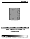
INTERFACES
9
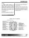
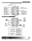
INSTALLING YOUR INTERFACE 6
Step 1.
Connect one end of the input cable to the
video output port of your source
computer and the 15-pin HD connector
end to the video input port of the
VA6803SX/ VA6804SX/ VA6805SX/
DA1926AV
.
Step 2.
Also connect one end of the audio input
cable to the audio output port of your
source computer and the 15-pin HD
connector end to the audio input
.
Step 3.
Connect the cable from a local monitor to
the local monitor output of the
VA6803SX/ VA6804SX/ VA6805SX/
DA1926AV
.
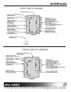
Step 4.
Also connect the audio cable from a local
audio amplifier to the local audio
output
of the
VA6803SX/ VA6804SX/
VA6805SX/ DA1926AV
.
Step 5.
Connect one end of coaxial cable
between a projector/monitor and the
BNC connectors on the side of the
VA6803SX/ VA6804SX/ VA6805SX/
DA1926AV
. Usually either a 4 BNC or 5
BNC coaxial cable is used, depending on
the display device’s requirement of
Composite SYNC (RGBS) or HSYNC &
VSYNC.
Step 6.
Also connect audio speaker wire from
the main sound system amplifier to the 5-
pin terminal block connector of the
VA6803SX/ VA6804SX/ VA6805SX/
DA1926AV
.
Step 7.
Connect the external power supply (AC
Adapter provided with the unit) with
2.5mm plug and 9V DC at 500mA output.
The power indicator light on the
VA6803SX/ VA6804SX/ VA6805SX/
DA1926AV
should turn on.
Step 8.
First, adjust the horizontal image
position using the monitor or projector
control. If further adjustments of the
image are needed, use the knob located
on the left side of the
VA6803SX/
VA6804SX/ VA6805SX/
Interface with
the Horizontal Position Control knob in
the ON position.
Step 9.
Adjust the red, green, and blue
equalization settings for the best image
quality.
OPERATION 7
The
VA6803SX/VA6804SX/VA6805SX/DA1926AV
will operate successfully as long as cables are
attached properly and other technical specifications
are followed. There are no other adjustments
necessary to operate the unit.
7.1 HORIZONTAL POSITION CONTROL
When in the OFF position, the switch will disable the
adjustment of the horizontal position of the image
through the dial located on the input side plate. If
the Horizontal Position knob is in the ON position,
the horizontal position control of image is possible
through the knob on the side of the
VA6803SX/
VA6804SX/VA6805SX/DA1926AV
.
With the
VA6803SX/ VA6805SX
’s Horizontal
Position knob in the OFF position (Horizontal
position control disabled), it is recommended to first
adjust the horizontal position of the image using the
monitor or projector’s Horizontal Position control. If
the horizontal position of the image needs further
adjustments, adjust it with the dial located on the
VA6803SX/ VA6805SX
Interface. The horizontal
position control is in the ON position at this time.
To adjust the horizontal position of the
VA6804SX
,
connect the provided cable (
CM11365
) to the unit.
Then adjust the horizontal position control knob
located on the cable.
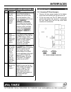
7.2 SYNC ON GREEN
Often systems that use large matrix switchers are
designed to switch signals in RGsB format. This is
done to reduce the cost of the switcher and cable. In
these types of systems, the ability of the
VA6803SX/
VA6804SX/ VA6805SX/ DA1926AV
to output Sync
on Green can be very helpful. It is important to note
that the
VA6803SX/ VA6804SX/ VA6805SX/
DA1926AV
will not separate sync from the green