


MULTI-TASKER
400-0401-001
5
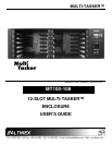
INSTALLING YOUR MT100-108 5
Step 1. Connect the power entry connector of the
MT100-108 to the power outlet with the
provided power cord. The power supply is
universal and will work throughout the
world with voltages from 110V-240VAC.
Step 2. If a control system is used to control the
cards in the MT100-108, connect the
RS-232 port of the MT100-108 to the
control system's RS-232 port. See
Table 4.
Connector on
Multi-Tasker™
Computer or
Control System
GND (Ground) Ground
RXD (Receive) Transmit
TXD (Transmit) Receive
Table 4. MT100-108 RS-232 Control
NOTE: Make sure the transmit pin of the control
unit is connected to the receive pin of the
MT100-108 and that the receive pin of the
control unit is connected to the transmit
pin of the MT100-108. See Figure 1 and
Figure 2.
Step 3. The unit is now operational.
OPERATION 6
The MT100-108, along with the MT101-115 front
panel, has many advanced remote control
capabilities, which are accessible through standard
RS-232 communication. The controlling can be
accomplished through a computer, a control
system, or any device capable of sending RS-232
commands. The factory settings for the RS-232
port are 9600 baud, 8 bits, 1 stop, and No parity.
Commands used for MultiTasker cards such as
[ON], [OFF], and [IO] that end in "S" will be saved
to memory. Commands not ending in "S" will still be
executed but will not be restored when the system
is reset (power off & power on again).
In this section, "Basic Enclosure" or "Unit" has the
same meaning. The basic enclosure is a complete
and independent card cage that has a controller
and 12 slots for plug-in cards. Each unit or basic
enclosure has its own Unit ID that is based on a
number from 0 to 9. Each plug-in card also has its
own Card ID that is a number from 1 to 12.
6.1 RS-232 CONNECTION
If a control system is used to control the cards in
the MT100-108 Multi-Tasker™ Basic Enclosure,
connect the RS-232 connector of the
MT100-108 to the control system's RS-232 port.
To connect the Multi-Tasker™ (MT) to a
computer or a terminal, you must have the
proper interface cable.
The RS-232 cable must have the appropriate
connector on each end and the internal wiring
must be correct. Connectors typically have 9
pins (DB-9 connector) or 25 pins (DB-25
connector) with a "male" or "female" pin
configuration. See Figures 1 and 2 for pinout
details.
Figure 1
DB9 Serial Connection
Figure 2
DB25 Connection