


SPECIAL APPLICATION
400-0210-001
8
INSTALLING YOUR PE1004CF 6
Step 1. Use ESD safety precautions and always
wear a ground strap when handling the
PE1004CF expansion card.
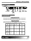
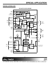
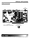
Step 2. Prepare the card per the drawing in
Diagram 4. Set SW2 for either hardware
or software equalization control and set
the power up default input. The gain
switch should remain in the X1 position.
Step 3. Turn off the power to the plasma display.
Step 4. Remove the card or cover currently
installed at the bottom of the display.
Step 5. Carefully, insert the PE1004CF. Use the
thumb screws to tighten the card.
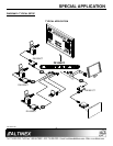
Step 6. Connect the video output connector of the
PE1004CF to a local display device with a
VGA type cable for RGBHV displays or a
YPbPr cable for component video.
Step 7. Connect the audio output connector of the
PE1004CF to speakers or amplifier using
the appropriate audio cable.
Step 8. Connect the CAT-5 inputs to their
respective CAT-5 transmitters using
standard CAT-5 type cable.
Step 9. If using RS-232 control, connect the
RS-232 input connector to the
communication port of the PC or other
control device. Use AVSnap or other
RS-232 communication software. Follow
the instructions defined in section 7.3 for
the IN command.
Step 10. Turn on power to the plasma display.
Step 11. Plasma display inputs 3, 4 and 5
correspond to PE1004CF inputs
CAT-5 #1, CAT-5 #2 and CAT-5 #3
respectively. Select input 3 on the plasma
display and CAT-5 #1 on the PE1004CF
will automatically be selected.
Step 12. Adjust the display properties for optimal
image quality.
OPERATION 7
7.1 RS-232 CONTROL
The PE1004CF has many advanced remote control
capabilities which are accessible through standard
RS-232 communication. Actual controlling may be
achieved using a computer control system or other
device capable of sending RS-232 commands.
7.1.1 RS-232 INTERFACE
The RS-232 commands, for the PE1004CF, are
in a simple ASCII character format.
1. Square brackets “[ ]” are part of the
command.
2. Use uppercase letters for all commands.
After processing a command, an “OK” will be
returned as feedback if the command is good.
Commands ending in ‘S’ will be saved into
memory. Commands not ending in ‘S’ will still be
executed but will not be restored after the
system is powered off.
7.2 DESCRIPTION OF COMMANDS
The default unit ID is zero, but may be set to a
value from 0 to 99. In single unit operation,
commands may be sent without the unit
identifier. Unit ID 0 should be used for single
unit operation.
If multiple PE1004CFs are connected to the
same communication port, the units may be
controlled in two different ways: either
individually, or more than one simultaneously.
In order to control all the units the same way
commands may be sent without the unit
identifier. Commands sent without the unit
identifier will be executed by all PE1004CFs.
Example:
[VER]: Executed by all units.
[VERC1]: For Unit ID 1 Only
[VERC2]: For Unit ID 2 Only
Individual control is accomplished by first
assigning each unit a unique ID number. Then
each unit may be controlled individually by
including the unit identifier at the end of each
command string.