


DESIGNER SOLUTIONS
400-0109-006
13
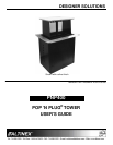
INSTALLING YOUR PNP400 6
Step 1. Refer to the ALTINEX website,
www.altinex.com, to download the latest
templates and instructions for tabletop
cutting requirements and installation.
In order to do this, locate the PNP400 on
the website and go to its detail page. The
links to the templates, user’s guide, and
more are on the left-hand side of the
screen.
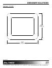
NOTE: The table can be 0.25-4.0 in
(6-102 mm) thick.
Step 2. Print all information applicable to the
installation of the PNP400, including the
templates and any detailed installation
instructions.
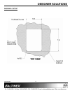
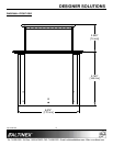
Step 3. Mark the table’s surface to indicate the
correct positioning of the unit. The face of
the unit is typically parallel to the longest
sides of the tables.
Step 4. Cut an opening into the table’s surface.
This operation should be performed by
experienced professionals in order to
insure accuracy and to be aesthetically
pleasing.
NOTE: Always confirm dimensions before
cutting to insure that specifications have
not changed.
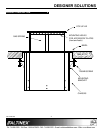
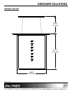
Step 5. Lower the PNP400 into the opening in the
table and make sure the bezel of the unit
sits evenly in the table.
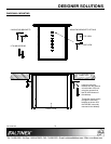
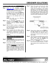
Step 6. From under the table, insert the mounting
brackets into the slots on the side of the
unit. See DIAGRAM 6 on page 10 for
details. Place the brackets at the desired
height for the table thickness and secure
them to the bottom of the table using the
thumb screws provided. There are two
support brackets, one for each side of the
unit.
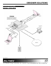
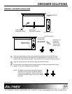
Step 7. Secure the power cord using the cable
clamp provided. Pass the power cord
(if any) from the bottom of the housing
and attach it to the table leaving a service
loop beneath the unit. Before tightening
the clamp, open and close the unit from
the top several times. Set the service loop
for smooth operation only. Do NOT leave
excessive cable hanging below the table.
Step 8. Secure other cables from the PNP400 to
the table separate from the power cord.
All cables should be secured using a
service loop to allow the unit to open and
close easily.
Step 9. Once you have connected power and the
proper cables to the unit, you may raise
the unit. To raise the PNP400 into
position, press the top of the unit.
Step 10. To lower the PNP400, push on the top of
the unit until it locks into place. Do NOT
use excessive force to press down on the
pop-up.