


ACCESSORIES
9
INSTALLATION 6
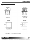
Step 1. Cut an opening into the table’s surface.
Refer to diagram 5 on page 8 of the
manual for table cutout requirements.
Note: The table can be 3 inches or thinner
in thickness. Always confirm dimensions
before cutting to insure that specifications
have not changed.
Step 2. Insert the TNP100UN into the opening in
the table.
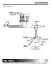
Step 3. Place the support brackets under the table
and place them between the support
mount grooves on the side of the
TNP100UN unit. Attach the brackets to the
groove at the desired height and secure
them to the bottom of the table using the 6-
32 nut. There are two support brackets,
one for each side of the unit. (See Figure
1)
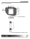
Figure 1: Attachment of the TNP100UN to a
table using support brackets and set screws
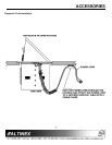
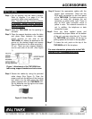
Step 4. Secure the cables by using the provided
cable clamp (See Figure 2). Pass the
power cord from the bottom of the housing
and attach it to the table using the cable
clamp supplied with the TNP100UN unit.
Do not keep the cord too tight or too loose
(See Diagram 4, page 7).
Figure 2: Cable Clamp
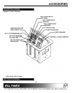
Step 5.Connect the appropriate cables with the
correct input connectors. There are two
RCA audio connectors on the front panel
of the TNP100UN. The black connector is
known as audio left, whereas the red
connector is called audio right. There is
also an RCA video connector, which is
yellow in color. The network connection is
red. In addition, the telephone or data
connection is gray.
Step 6. Once you have applied power and
connected the proper cables on the bottom
of the unit, you may raise the unit. To raise
the TNP100UN into position, lift the top by
pulling upward at the notch in the top plate.
Step 7. To lower the unit, push on the top of the
TNP100UN until it fits into place.
For more information, please refer to the FAQ
Section or the Troubleshooting Guide.