


INTERFACES
11
CB5100PL-
5BM02005BM
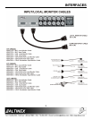
200 ft, 5 BNC M to 5 BNC M
CB5100PL-
5BM02505BM
250 ft, 5 BNC M to 5 BNC M
All MS81 series cables listed above are 3 ft. long.
These cables are also available in 6 ft. and 12 ft.
lengths. Please call 1-714-990-2300 for a wider
selection of cables.
FAQ (FREQUENTLY ASKED QUESTIONS) 9
No: Question Answer
1 Why does
the
termination
switch have
to be “ON”?
The termination switch
should be ON if the local
monitor is connected
through a straight cable. It
will be OFF only if a monitor
breakout cable is used at the
local monitor output
connector.
2 When and
why do I
need to use
the
“Horizontal
Position”
Control dial?
The “Horizontal Position”
Control dial enables or
disables the control of the
Horizontal Position of the
image. First adjust the
horizontal position using the
monitor or projector control,
and then use the horizontal
position control on the
VA6835FC, if needed.
3 What dip-
switch do I
set to receive
the
composite
sync output?
If the desired output signal is
composite sync, turn OFF
the “HV OUTPUT” dip-switch
and connect only 4 wires
(RGBS) to the red, green,
blue, and sync connectors.
4 When and
why would I
use the
“Sync on
Green” dip-
switch,
although the
unit does not
separate
Sync from
Green?
The VA6835FC separates
the sync signal from green if
the input is RGsB, so the
output can be either RGBS
or RGBHV. This dip-switch
should be OFF if the desired
output is RGBS or RGBHV
for any type of input.
5 When do I If the desired output is in
use the
“HV OUT”
dip-switch?
RGBHV format, turn ON the
“HV OUT” dip-switch. If the
“HV OUT” dip-switch is OFF,
the output signal may have
composite sync present on
the horizontal sync
connector.
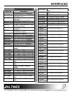
6 What is a
Common
Computer
Video Card
pin-out?
See the following table for
Common Computer Video
Card pin-outs that can be
used with the VA6835FC.
PIN
No.
MAC VGA SUN
A1
n/a n/a Red
A2
n/a n/a Green
A3
n/a n/a Blue
1
Red Gnd Red N/C
2
Red Green N/C
3
C.Sync Blue Sense
4
ID Bit 01 ID Bit Sense Rtn
5
Green N/C C. Sync Sens
6
Green Gnd. Red Rtn. N/C
7
ID Bit 02 Green Rtn. N/C
8
N/C Blue Rtn. N/C
9
Blue N/C N/C
10
ID Bit 03 Gnd N/C
11
C/V Gnd. ID Bit
12
V. Sync ID Bit
13
Blue Gnd. H. Sync.
14
H. Gnd V. Sync
15
H. Sync N/C
Table 8. Common Computer Video Card pin-outs