


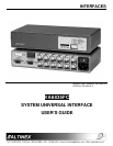

INTERFACES
8
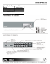
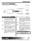
APPLICATION DIAGRAM 5
INSTALLING YOUR INTERFACE 6
Step 1. Please attach the Interface on the rack
using the provided rack mount hardware
on or under the furniture using the
optional TM Series Altinex brackets.
Step 2. Before you plug in the power cord to the
unit, please verify that the voltage rating
of 110V/220V on the FUSE CLIP located
at the rear of the unit is the same as the
power outlet. (Refer to section 4.6 for
changing the voltage).
Step 3. Connect one end of the input cable
included with the Interface unit to the
video output connector of your computer
and the other end to the computer input
HD-15 port of the VA6835FC.
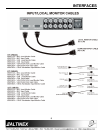
Step 4. If needed, connect the local monitor
output HD-15 connector of the VA6835FC
to the local monitor using the appropriate
Altinex Local Monitor cables. It is not
necessary to terminate this output with a
termination plug if a local monitor is not
being used.
Step 5. Connect one end of a BNC cable to
output one or two of the VA6835FC units.
Connect the other end to the RGB input
on the projector or monitor. Usually either
a 4 BNC or 5 BNC coaxial cable is used,
depending on whether display devices
require composite sync or horizontal and
vertical sync signals.
Step 6. Make sure that the dip-switches are set
properly. For the desired sync output
format, refer to section 7.
Step 7. It is recommended that when the
Interface’s horizontal position control is
centered (or turned OFF), the horizontal
position of the image should first be
adjusted using the control provided by the
monitor or projector. If it is still required, it
can be adjusted using the Horizontal
Position Control dial located on the front
of the VA6835FC.
CONGRATULATIONS! YOU ARE DONE.
If you experience any problems, please call
1-800-258-4623 or 1-714-990-2300 for
international calls.