


Hardware Installation- 21 -
English
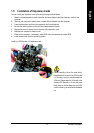
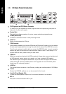
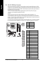
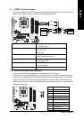
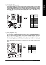
8) F_PANEL (Front Panel Jumper)
Please connect the power LED, PC speaker, reset switch and power switch etc of your chassis front
panel to the F_PANEL connector according to the pin assignment below.
HD (IDE Hard Disk Active LED) Pin 1: LED anode(+)
Pin 2: LED cathode(-)
SPEAK (Speaker Connector) Pin 1: Power
Pin 2- Pin 3: NC
Pin 4: Data(-)
RES (Reset Switch) Open: Normal
Close: Reset Hardware System
PW (Power Switch) Open: Normal
Close: Power On/Off
MSG(Message LED/Power/Sleep LED) Pin 1: LED anode(+)
Pin 2: LED cathode(-)
NC NC
12
19
20
HD-
HD+
RES+
RES-
NC
SPEAK-
MSG-
MSG+
PW-
PW+
SPEAK+
Message LED/
Power/
Sleep LED
Power Switch
Speaker Connector
IDE Hard Disk
Active LED
Reset Switch
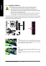
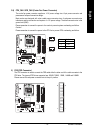
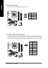
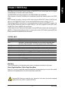
9) F_AUDIO (Front Audio Panel Connector)
If you want to use Front Audio connector, you must remove 5-6, 9-10 Jumper.
In order to utilize the front audio header, your chassis must have front audio connector. Also please
make sure the pin assignments for the cable are the same as the pin assignments for the front audio
header. To find out if the chassis you are buying support front audio connector, please contact your
dealer. Please note, you can have the alternative of using front audio connector or of using rear audio
connector to play sound.
Pin No. Definition
1 MIC
2 GND
3 MIC_BIAS
4 POWER
5 FrontAudio(R)
6 Rear Audio (R)/ Return R
7NC
8 No Pin
9 FrontAudio (L)
10 Rear Audio (L)/ Return L
1
10
9
2