


Single Beep - a short power loss has
occurred and the Back-UPS briefly
goes on battery.
Four Beeps Every 30 Seconds - this
alarm is sounded whenever the Back-
UPS is running On Battery. Consider
saving work in progress.
Continuous Beeping - this alarm is
sounded whenever a low battery
condition is reached. Battery run-time
is very low. Promptly save any work
in progress and exit all open
applications. Shutdown the operating
system, computer and the Back-UPS.
Back-UPS
™
350/500
User’s Manual
990-2101 4/01
Installation
3
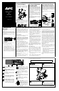
Connect Equipment
Battery Back Up Outlets (qty. of 3). These
outlets provide battery back-up, surge protection,
and Electro-magnetic Interference (EMI) filtering.
In case of power outage, battery power is
automatically provided to these outlets. Power
(facility or battery) is not supplied to these outlets
when the Back-UPS is switched Off. Connect a
computer, monitor, external disk or CD-ROM
drive to these outlets.
Surge Only Outlets (qty. of 2). These outlets are
always On (when facility power is available) and
are not controlled by the On/Off switch. These
outlets do not provide power during a power
outage. Connect a printer, fax machine or scanner
to these outlets.
Cable Management Feature. For convenience,
the Back-UPS provides a method for integral cable
management (see below).
Battery Back Up
Outlets (3)
Surge Only
Outlets (2)
Cable
Management
Feature
Note: Allow the Back-UPS to charge for a full eight
hours prior to use.
Caution: The plug on the supply cord is the
disconnect device for the product. The socket-outlet
that you plug into shall be located near the equipment
and shall be easily accessible. The socket outlet must
be a grounding type.
Press the Power On/Off push-button on the Back-
UPS.
Observe that the following events occur after
pressing and releasing the push-button:
• The green On-Line indicator flashes.
• The yellow On Battery indicator lights while
the Self-Test is being performed.
• When Self-Test has successfully completed,
only the green On Line indicator will be lit.
• If the internal battery is not connected, (see step
1) the green On Line indicator and red Replace
Battery indicator will light. The Back-UPS will
also emit a series of short beeps for one minute.
Power On/Off
Push-button
6
Connect USB Cable and Install Software (optional)
On Line (green) - is lit whenever facility
power is powering the Battery Backup
outlets.
On Battery (yellow) - is lit whenever the
battery of the Back-UPS is powering
equipment connected to the Battery Back
Up Outlets.
ON LINE ON BATTERY OVERLOADREPLACE BATTERY
Status Indicators and Alarms
1
4
Connect the Phone
Line to Surge Protection
The telephone ports provide lightning surge
protection for any device connected to the telephone
line (computer, modem, fax or telephone). The
telephone ports are compatible with Home Phoneline
Networking Alliance (HPNA) and Digital Suscriber
Line (DSL) standards, as well as all modem data
rates. Connect as shown.
The optional USB Data Port connection is described
in step 5.
Wall Outlet
Modem/Phone/Fax
Computer USB
1 2 3
4 5 6
7 8 9
0
*
#
Back-UPS
(end view)
Port
Mac OS 9 (9.0.4 or higher) Users
APC Shutdown Manager software has been designed
specifically to work with Mac OS 9 (9.0.4 or higher,
except OS X). There are builds of the Mac OS prior to
Mac OS 9.0.4 with power drivers that have known
problems. Ensure that the most up to date version of
Mac OS 9 (9.0.4 or higher) is installed on the system.
Insert the APC Installation CD-ROM with the APC
Shutdown Manager software into the CD-ROM drive.
An icon called “APC Shutdown Manager v1.0” will
appear on the computer desktop. Open the folder and
double-click the “ReadMe” file. Ensure that the
computer’s hardware matches the requirements stated
in the ReadMe file. Double-click on “APC Shutdown
Manager v1.0” to begin the installation of the
software. At the first dialog, click on “Continue”.
Read the displayed license agreement and click
“Accept” to agree to the terms. Click on “Install” to
begin. After installation, click on the “Restart” dialog
button to restart the computer.
All Other Users
The software is designed for the Windows and
Macintosh operating systems mentioned in this
section. If one of these operating systems is not
installed on the computer, the Back-UPS will still
provide these primary features:
• Battery backup, surge protection, and telephone
line protection to protect the entire desktop from
lightning and power surges.
• Runtime needed to work through brief power
disturbances. This allows time to manually save
data and shut down safely.
The disabled features include Unattended Automatic
Operating System Shutdown and Application Data
Saving.
Replace Battery (red) - is lit when-
ever the battery is near the end of its use-
ful life, or if the battery is not connected
(see above). A battery that is near the
end of its useful life has insufficient run-
time and should be replaced.
Beeps for 1 Minute Every 5 Hours -
this alarm is sounded whenever the
battery has failed the automatic
diagnostic test.
ES
to the Back-UPS
5
Switch on the
Back-UPS
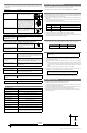
Replace the Internal Battery
To replace the internal battery, proceed as follows:
Note: Replacing the battery is a safe procedure. However, small sparks may occur
during the process. This is normal.
Connect the new battery to the battery connector.
Pull the battery out of the housing, exposing the
battery wire and connector. Pull up on the battery
Place the unit on a flat surface. Press the battery
cover latch and remove the battery cover.
Slide the tabs on the battery cover into the slots
Place the battery into the housing. in the chassis. Push the battery cover downward
connector. Recycle the old battery.
until the battery cover latchs to the housing.
1
2
3
4
5
6
1 2 3 4
5
6
APC and Back-UPS are registered trademarks of
American Power Conversion. All other trademarks are property
of their respective owners.
Connect Battery
1
2
3
4
5
The Back-UPS is shipped with the internal battery
disconnected. Remove the battery cover and
connect the battery, as shown below. Refer to
Replacing the Battery for additional information.
Avoid placing the Back-UPS in direct sunlight,
excessive heat, excessive humidity or in contact
with fluids of any type. For convenience, the
Back-UPS can be mounted on a wall (see Wall
Mount of UPS on the back page).
2
Placement
Overload (red) - is lit whenever power
demand has exceeded the capacity of the
Back-UPS.
Continuous Tone - this alarm is
sounded whenever the Battery Backup
outlets are overloaded.
Circuit Breaker - the circuit
breaker button located at the side
of the Back-UPS will stick out if
an overload condition forces the
Back-UPS to disconnect itself
from facility power. If the button
sticks out, disconnect non-
essential equipment. Reset the
circuit breaker by pushing the
button inward.
Circuit
Breaker
w w w
.apc.com
®
Note: The Back-UPS software CD-ROM provides
data reporting and unattended shutdown of the
computer connected to the device. The User’s
Guide contains additional information about the
Back-UPS software. The User’s Guide is
contained in the main folder contained in the CD-
ROM.
Attention: USB Hubs
The Back-UPS should be plugged into the USB
port of the computer, not into a USB hub.
The computer must be powered On before
connecting the USB cable. Connect the USB cable
end (USB symbol facing down) to the USB data
port located on the side of the Back-UPS. Connect
the other end of the USB cable to the USB port on
the rear panel of the computer.
Windows 98
®
and Windows Me
®
Users
The APC Power Management Extensions
software has been designed specifically to work
with Windows 98 build number 4.10.1998,
Windows 98 SE (Second Edition) 4.10.2222A,
and Windows Me (Millennium Edition).
To ascertain the build number, go to the Control
Panel, open the System dialog and view the
System information under the General tab of the
dialog. To install the software, perform the
following steps:
1. Please skip to step 4 if running Windows Me.
For Windows 98, after connecting the USB
cable, the “Add New Hardware Wizard” dialog
box is displayed. Insert a Windows 98
operating system CD into the computer CD-
ROM drive before proceeding.
2. Follow the installation instructions on the
computer screen.
During installation, Windows will need to
search for new drivers. When prompted, make
sure the CD-ROM drive box is checked.
3. After installation of the drivers is complete, a
“Windows 98 CD-ROM” dialog box may
appear. If this happens, just close the box.
4. Insert the APC Installation CD-ROM into the
computer’s drive. The software user
documentation is a file on the main folder of
the CD. The filename is Users Guide.pdf.
5. Follow the installation instructions on the
computer screen.
If the software does not automatically install,
the Windows autorun feature may have been
disabled. In this case: Choose “Start” in the
taskbar and then the “Run” option. Type the
following: <CD-ROM drive letter>:\setup.exe.
Click “OK”.
6. After the installation is complete, the APC plug
icon will appear in the taskbar (near the clock).
To view the Power Management user interface,
double-click on the APC plug taskbar icon or,
alternatively, choose: Start > Settings >
Control Panel > Power Management.
Note: Windows 98 and Windows Me categorize a
UPS as an HID (Human Interface Device). The
Back-UPS is listed in: Control Panel > System >
Device Manager > HID category > HID
Compliant Device.
Windows 2000
®
Users
The CD-ROM included with this package
contains a “wizard” that optimizes a computer
system’s power settings for operation with the
Back-UPS. It does this by changing various
settings in Power Options Properties in the
Control Panel. APC strongly advises that the
computer system be reconfigured by running this
wizard.
1. Insert the APC Power Management CD-ROM
into the computer’s drive.
2. Choose “Start” and then the “Run” option.
Type: <CD-ROM drive letter>:\setup.exe.
Click “OK” and follow the instructions.