


✔
✔
✔
✔
✔
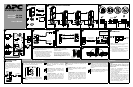
CONNECT TVSS
Back-UPS
®
RS 1000
User’s Manual
Back-UPS
®
RS 1500
1
®
CONTENTS
RJ-45USB
RJ-11RJ-11
2
CONNECT BATTERY CARTRIDGE
4
CONNECT EQUIPMENT / POWER
Monitor
Printer or Scanner
FAX
External Disk or
CD / DVD Drive
10
INSTALL SOFTWARE ON
COMPUTER
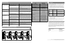
There are four status indicators (lights) on the
front panel of the Back-UPS (On Line, On
Battery, Overload, and Replace Battery).
On Line (green) - is lit whenever utility
power is powering the Battery Backup
outlets.
On Battery (yellow) - is lit whenever the
battery of the Back-UPS is powering
equipment connected to the Battery
Backup Outlets.
Four Beeps Every 30 Seconds - this
alarm is sounded whenever the Back-UPS
is running On Battery. Consider saving
work in progress.
Overload (red) - is lit whenever power
demand has exceeded the capacity of the
Back-UPS.
Continuous Tone - this alarm is sounded
whenever the Battery Backup outlets are
overloaded.
Circuit Breaker - the circuit breaker button
located on the rear panel of the Back-UPS
will stick out if an overload condition forces
the Back-UPS to disconnect itself from
utility power. If the button sticks out,
disconnect non-essential equipment. Reset
the circuit breaker by pushing the button
inward.
Replace Battery (red) - is lit whenever the
battery is near the end of its useful life, or
if the battery is not connected (see above).
A battery that is near the end of its useful
life has insufficient run-time and should be
replaced.
Chirps for 1 Minute Every 5 Hours - this
alarm is sounded whenever the battery has
failed the automatic diagnostic test.
Continuous Beeping - this alarm is
sounded whenever a low battery condition
is reached. Battery run-time is very low.
Promptly save any work in progress and
exit all open applications. Shutdown the
operating system, computer and the Back-
UPS.
NOTE: Macintosh Users - for full USB
performance, use OS 9.22 or higher.
If Autoplay is not enabled on the computer,
proceed as follows:
1. On the computer desktop of the display,
double-click on My Computer.
2. Double-click on the CD-ROM drive icon
and follow the on-screen instructions.
11
GROUND
The Back-UPS features a transient
voltage surge-suppression (TVSS)
screw for connecting the ground lead
on additional surge suppression devices
such as network and data line surge
protectors.
Wall
Outlet
Modem/
Phone/Fax
TVSS GND
From Data Line
TVSS
Follow the
on-screen
instructions.
On Line
On Battery
Overload
Replace Battery
w
w
w
.apc.com
®
STATUS INDICATORS AND ALARMS
✔
SERVICE
If the Back-UPS arrived damaged, notify the
carrier.
If the Back-UPS requires service, do not
return it to the dealer. The following steps
should be taken:
1. Consult the Troubleshooting section to
eliminate common problems.
2. If the problem persists, go to http://
www.apc.com/support/.
3. If the problem still persists, contact APC
Technical Support.
4. Have the Back-UPS model number, serial
number and date of purchase available. Be
prepared to troubleshoot the problem with an
APC Technical Support representative. If
this is not successful, APC will issue a
Return Merchandise Authorization (RMA)
number and a shipping address.
7
To Computer USB
Port
CONNECT INTERFACE CABLE
Data Port
BR24BP Battery Pack
Computer
RJ-45USB
For connection of APC’s optional
external 24-volt battery pack
(BR24BP) to the Back-UPS RS 1000
3
5
Phone Jack
Computer
Modem Port
CONNECT PHONE/MODEM/FAX
TVSS GND
Wall
Outlet
Wa ll
Outlet
Modem/
Phone/Fax
6
CONNECT 10/100 Base-T or VOIP
Network Jack
Computer
Network Port
Note: Allow the Back-UPS to charge for a
full eight (8) hours prior to use.
Press the front panel Power ON/OFF switch
and observe that the following events occur
after pressing and releasing the switch:
• The green On Line indicator flashes.
• The yellow On Battery indicator lights
while a Self-Test is being performed.
• When Self-Test has successfully
completed, only the green On Line
indicator will be lit.
• If the internal battery cartridge is not
connected (see Step 2 above), the green
On Line indicator and red Replace Battery
indicators will light. The Back-UPS will
also emit a chirping sound.
8
SWITCH ON THE BACK-UPS
9
ORIENTATION
10/100 Base-T
VOIP
✘✔✔
Computer
3
OPERATING ENVIRONMENT
32 - 104
o
F (0 - 40
o
C)
✔
✘
24 inches
60 cm
✔
BATTERY
BACKUP
SURGE ONLY
OR
and Back-UPS RS 1500.