


6HWXS
Back-UPS Pro
®
350 / 500
User’s Manual
990-2052B Revision 3 5/99
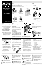
&RQQHFWEDWWHU\ZLUH
The UPS is shipped with one battery wire disconnected - in compliance with Department of Transportation
(DOT) regulations. Connect the battery wire as shown.
The UPS will not operate unless the steps below are performed.
a. Set the UPS at the edge b. Slide the battery c. Grasp the tab attached to the
of a table. compartment cover down. battery and slide the battery
partially out. Connect the black
wire to the battery by pushing it all
the way onto the terminal. Small
sparks are normal.
d. Slide the battery back in. e. Slide the battery compartment
Avoid pinching the wires. cover back into place.
3ODFH3RZHU836
Place the UPS to avoid:
• Direct sunlight.
• Excessive heat.
• Excessive humidity or contact with liquids.
Plug the UPS directly into a wall outlet.
• The Building Wiring Fault indicator may flash
momentarily while being plugged in.
• The UPS begins charging when connected to
utility power.
• Four hours of charging should be sufficient to
achieve maximum battery capacity.
&KHFNWKH%XLOGLQJ
:LULQJ)DXOWLQGLFDWRU
If the Building Wiring Fault indicator on the power
plug stays lit, one of the following conditions exist:
• Open or high resistance ground.
• Hot and neutral polarity reversal.
• Overloaded neutral circuit.
A lit indicator means that a possible shock
hazard exists. Improper building wiring should
be corrected by a qualified electrician.
Note: Improper building wiring will not prevent the
UPS from operating, but will limit its protection
capability. Improper building wiring could result
in equipment damage that is not covered by
APC. Please refer to APC’s Equipment
Protection Policy for details.
&RQQHFWHTXLSPHQWWR
836
Do not plug surge protectors or power strips into
Battery Backup outlets.
Battery Backup Plus Surge Protection outlets (4)
Data sensitive equipment such as a computer,
monitor, and external drives should be powered by
these outlets. Battery power is automatically
provided in case of power outage. Power (utility or
battery) is not supplied to these outlets when the
UPS is switched Off.
Surge Protection outlets (3)
Equipment such as a printer, fax machine, scanner,
or even a desk lamp should be powered by these
outlets. These outlets do not provide power during a
power outage. These outlets are always on (when
utility power is available) and are not controlled
by the front panel switches.
Transformer Block outlets (2)
One Battery Backup Plus Surge Protection and one
Surge Protection outlet accept transformer blocks.
Typical Installation
Black Velcro Cord Straps (2 - not shown)
Straps can be used to manage cords.
&RQQHFWSKRQHFDEOHVWR
VXUJHSURWHFWLRQ
The UPS can protect up to two telephone lines on
one phone cable. Connect your modem/fax/phone
as shown with the release tab facing up for the
ends connected to the UPS.
6ZLWFK2Q7HVWWKH836
Press the On/Test button.
You will observe the following events after
pressing and releasing the On/Test button:
• The green On Line indicator will flash.
• The yellow On Battery indicator will light
while a battery test is performed.
• When the self test has successfully completed,
only the green On Line indicator will be lit.
• The red Overload indicator may flash briefly
when the UPS is switched on.
Following the test, if a red indicator is lit or you
want to perform a self test, consult the
troubleshooting section.
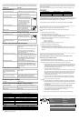
&RQQHFW86%FDEOHDQG
LQVWDOOVRIWZDUH
RSWLRQDOSURFHGXUH
Your computer system must be On before starting
this procedure. Have your Windows 98 operating
system CD ready.
Connect the USB cable end, with USB symbol
facing down, to the UPS. Connect the other USB
cable end directly to an available USB port on your
computer.
USB connection on rear panel of UPS:
1. After connecting the USB cable, the
Windows 98 "ADD NEW HARDWARE
WIZARD" dialog box is displayed. Insert
your Windows 98 operating system CD into
the computer’s CD-ROM drive before
proceeding.
2. Follow the installation instructions on your
computer screen.
During installation, Windows will need to
search for new drivers. When prompted,
make sure the CD-ROM drive box is checked.
3. After installation is complete, a "Windows 98
CD-ROM" dialog box may appear. If this
happens, just close the box.
4. Remove the Windows 98 Operating System
CD from the CD-ROM drive.
5. Insert the APC Power Management
Extensions for Windows 98 CD into the
computer’s CD-ROM drive.
The software user guide is a file on the CD.
Its filename is User’s Guide.pdf.
6. Follow the installation instructions on your
computer screen.
If the software does not automatically install,
your Windows 98 auto run feature may have
been disabled.
To install:
a. Click “Start”.
b. Click “Run”.
c. Enter the path to the setup.exe file on
the CD-ROM drive:
CD-ROM drive letter:/setup.exe
d. Click “OK”.
7. After installation is complete, the APC plug
Task Bar icon will appear on your Task Bar
(near the clock). To start the Power
Management application Double-click on the
APC plug Task Bar icon or start the Power
Management applet in the Windows 98
control panel.
6WDWXV,QGLFDWRUV
There are four indicator lights and a speaker grille on the
front panel to indicate UPS status.
On Line (green) - This indicator is lit whenever
conditioned utility power is powering the Battery
Backup outlets.
Single Beep - This alarm is sounded whenever
the On/Test button is pressed.
On Battery (yellow) - This indicator is lit
whenever utility power is outside safe limits and the
UPS battery is powering the Battery Backup outlets. If
the outage is extended, APC software can close
software applications, and then shut down the operating
system and the UPS.
Four Beeps Every 30 Seconds - This alarm is
sounded whenever the UPS is running On
Battery.
Continuous Beeping - This alarm is sounded
whenever a low battery condition is reached.
Battery runtime is very low. Promptly save your data,
exit all applications, and then shut down the operating
system.
Overload (red) - This indicator is lit whenever
equipment connected to Battery Backup outlets is
drawing more power than the UPS can provide. Move
one or more pieces of equipment to the Surge
Protection outlets.
Continuous Tone - This alarm is sounded
whenever the Battery Backup outlets are
overloaded.
Circuit Breaker - The circuit
breaker button will stick out if
an overload condition forces
the UPS to disconnect itself
from utility power. If the
button sticks out, disconnect
non-essential equipment and reset the circuit breaker by
pushing the button in.
Replace Battery (red) - This indicator is lit
whenever the automatic diagnostic test has determined
the battery is near the end of its useful life. The battery
should be replaced within two weeks (see Order
Replacement Battery). Failure to replace the battery
may result in insufficient runtime during a power
outage.
Chirps for 1 Minute Every 5 Hours - This
alarm is sounded whenever the battery has
failed the automatic diagnostic test.
APC and Back-UPS Pro are registered trademarks of
American Power Conversion.
Modem/Fax/Phone
Wall
Outlet
Monitor
Computer
External
Drive
Printer
Fax
Scanner