


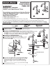

M965227
Speed Connect™ Drain
Troubleshooting Guide
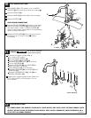
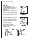
Disconnect the Cable from the Drain by threading the Cable Connector (1) counter-clockwise. Fig. A.
Look at the area on the Drain Body where the Cable was attached and locate the component labeled
as “Cam” and “Cam Cap” in the illustration. Fig. B.
Use fingers or small screwdriver under either side of the Cam Cap to pry it out from the Drain. Fig. D.
Remove the Cam by pulling it straight out while wiggling gently to loosen the Rubber Seal. Fig. E.
The Stopper can now be removed by lifting it out of the Drain. Fig. F.
CAM
CAM CAP
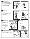
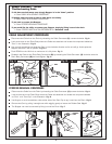
CABLE ADJUSTMENT PROCEDURE
If sink does not hold water even though Stopper is in the “down” position:
• Follow CABLE ADJUSTMENT PROCEDURE.
If Stopper does not raise up fully or sink drains too slowly:
• Follow CABLE ADJUSTMENT PROCEDURE.
If you need to remove the Stopper:
• Follow STOPPER REMOVAL PROCEDURE.
If you would like the ability to remove your Stopper simply by lifting it out of the drain:
• Follow STOPPER INSTALLATION PROCEDURE for “Unlocked” mode.
Fig. B.
REMOVE
CAM
Fig. E.
Fig. F.
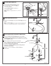
Disconnect the Cable from the Drain by threading the Cable Connector (1) counter-clockwise. Fig. A.
Look at the area on the Drain Body where the Cable was attached and locate the component labeled as
“Cam” in the illustration. Fig. B.
Use a small screwdriver to rotate the Cam in the clockwise direction as far as it will go. At this point the
Stopper should be in the UP position. Fig. B, C.
Push DOWN on the Lift-Knob to make sure it is fully down. Fig. C.
Re-attach the Cable to the Drain Body Connection (2) by threading the Cable Connector (1) clockwise onto the
Drain Body Connection (2) and hand-tighten. Fig. A.
STOPPER REMOVAL PROCEDURE
2
1
RE-ATTACH
DISCONNECT
Fig. D.
REMOVE
CAM CAP
5
Fig. A.
Fig. C.
STOPPER
DOWN