


Chapter 3 Signals and Pinout Tables
40 Reference Manual COM 830
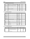
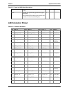
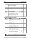
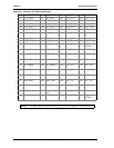
IDE_IOR# I/O read line to IDE device. O 3.3V
IDE_REQ IDE Device DMA Request. It is asserted by the
IDE device to request a data transfer.
I 3.3V
IDE_ACK# IDE Device DMA Acknowledge. O 3.3V
IDE_CS1# IDE Device Chip Select for 1F0h to 1FFh range. O 3.3V
IDE_CS3# IDE Device Chip Select for 3F0h to 3FFh range. O 3.3V
IDE_IORDY IDE device I/O ready input. Pulled low by the IDE
device to extend the cycle.
I 3.3V PU 4k7
3.3V
IDE_RESET
#
Reset output to IDE device, active low. O 3.3V
IDE_IRQ Interrupt request from IDE device. I 3.3V PU 8k2
3.3V
IDE_CBLID# Input from off-module hardware indicating the
type of IDE cable being used. High indicates a 40-
pin cable used for legacy IDE modes. Low
indicates that an 80-pin cable with interleaved
grounds is used. Such a cable is required for Ultra-
DMA 66, 100 and 133 modes.
I 3.3V PD 10k
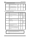
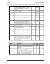
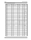
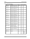
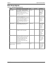
Table 3-19. PCI Express Signal Descriptions (x16 Graphics)
Signal Description I/O PU/PD Comment
PEG_RX[0-15]+
PEG_RX[0-15]-
PCI Express Graphics Receive Input differential
pairs. Some of these lines are multiplexed with
SDVO lines.
Note: Can also be used as PCI Express Receive
Input differential pairs 16 through 31 known as
PCIE_RX[16-31] + and -.
I PCIE
PEG_TX[0-15]+
PEG_TX[0-15]-
PCI Express Graphics Transmit Output
differential pairs. Some of these lines are
multiplexed with SDVO lines.
Note: Can also be used as PCI Express Transmit
Output differential pairs 16 through 31 known
as PCIE_TX[16-31] + and -.
O
PCIE
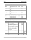
PEG_LANE_RV
#
PCI Express Graphics lane reversal input strap.
Pull low on the carrier board to reverse lane
order. Be aware that the SDVO lines that share
this interface do not necessarily reverse order if
this strap is low.
I
1.05V
PEG_LANE
_RV# is a
boot strap
signal (see
note below)
PEG_ENABLE# Strap to enable PCI Express x16 external
graphics interface. Pull low to disable internal
graphics and enable the x16 interface.
I 3.3V PU 10k
3.3V
NOTE Some signals have special functionality during the reset process. They may bootstrap
some basic important functions of the module.
Table 3-18. IDE Signal Descriptions (Continued)