


Installation
4
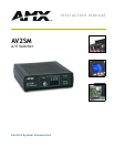
AV2SM A/V Switcher
Wiring Guidelines
The maximum wiring distance between the Central Controller and the AV2SM is determined by
power consumption, supplied voltage, and the wire gauge used for the cable. The maximum wiring
lengths for using AXlink power are based on a minimum of 13.5 volts available at the Central
Controller’s power supply. The maximum lengths allowable between the AV2SM and the Central
Controller are as follows:
Preparing captive wires
1. Strip 0.25 inch of wire insulation off all wires.
2. Insert each wire into the appropriate opening on the connector according to the wiring
diagrams and connector types described in this section.
3. Tighten the screws to secure the wire in the connector. Do not tighten the screws excessively;
doing so may strip the threads and damage the connector.
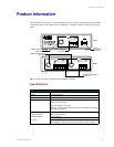
Video output connector
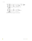
Connect your output display monitor to the VIDEO connector on the front panel using FIG. 4.
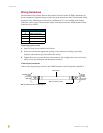
Wiring Guidelines
Wiring size Maximum wiring length
18 1805.7 ft (550.37 m)
20 1142.4 ft (382.20 m)
22 712.2 ft (217.07 m)
24 448.9 ft (136.82 m)
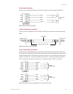
FIG. 4 VIDEO OUTPUT wiring diagram
Output
display
monitor
connector
(female)
AV2SM video
output
connector
(female)
Video Cable
BNC connectors (male)