


Installation
5
AV2SM A/V Switcher
Audio output connector
Connect your output display monitor to the Audio connector on the front panel using FIG. 5.
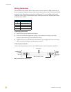
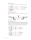
Video A and B input connectors
Connect your Video Output source to the Input A and B Video connector on the rear panel using
FIG. 6.
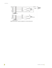
Audio A and B Input connectors
Connect the two Audio Output sources to the Input A and B Audio connectors, FIG. 7 illustrates
the automatic switching mode; FIG. 8 shows the wiring for manual switching mode. When you use
manual switching mode, the Select pin (rear panel) is taken low to select the B source and high to
select the A source. A low can be an external relay closure or a voltage level from 0 VDC to 0.8
VDC. A high can be an open set of contacts or a voltage level from 3.3 VDC to 12.0 VDC.
FIG. 5 AUDIO OUTPUT wiring diagram
FIG. 6 VIDEO INPUT A and B wiring diagram
FIG. 7 AUDIO INPUT A and B wiring diagram for automatic switching mode
AV2SM AUDIO
LEFT
GND
GND
RIGHT
LEFT
GND
GND
RIGHT
INPUT connector
Audio source
output
Video input
source
connector
(female)
AV2SM video
input A and B
connectors
(female)
Video Cable
BNC connectors (male)
LEFT
LEFT
GND
GND
RIGHT
GND
SELECT
LEFT
GND
GND
RIGHT
GND
LEFT
GND
GND
RIGHT
LEFT
GND
GND
RIGHT
AV2SM
AUDIO INPUT A
AV2SM
AUDIO INPUT A
Output
(audio source)
Output
(audio source)