


Configuration and Installation
7
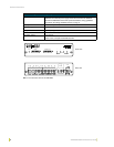
AXB-IRS4 IR/Serial Interface (4 Ports)
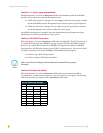
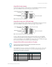
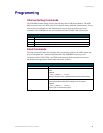
Using AXlink for data and power
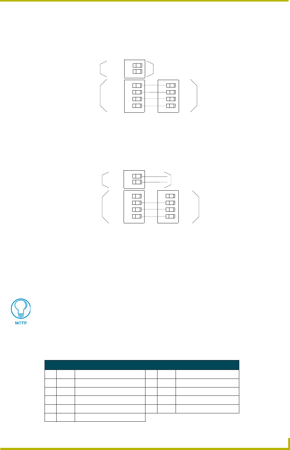
Connect the Central Controller's AXlink connector to the AXlink/RS-232 connector, on the rear
panel of the AXB-IRS4, for data and 12 VDC power, as shown in FIG. 6.
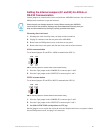
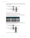
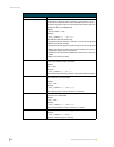
Using AXlink for data and a 12 VDC power supply
Connect the Central Controller's AXlink connector to the AXlink/RS-232 connector, on the rear
panel of the AXB-IRS4, and the optional 12 VDC power supply, as shown in FIG. 7.
Use the 12 VDC power supply when the distance between the AMX system and AXB-IRS4
exceeds the limits described in the Wiring Guidelines at 125 mA table on page 6. Make sure to
connect only the GND wire on the AXlink/RS-232 connector when using a 12 VDC power supply.
Do not connect the PWR wire to the AXlink connector's PWR opening.
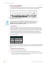
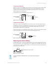
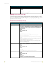
Using the AXlink-to-DB-9 connector cable for a PC system
The AXlink/RS-232 connector, on the back of the AXB-IRS4, can be connected to a PC system
using a DB-9 connector cable. Connector pins 2, 3, and 5 are used for data and ground. The
following table lists the DB-9 wiring pinouts.
FIG. 6 AXlink data and power wiring diagram
FIG. 7 AXlink and optional 12 VDC power supply wiring diagram
PWR (+)
GND (-)
PWR(+) PWR
AXM/RX AXM
AXP/TX AXP
GND (-)
GND
12 VDC PWR connector
on AXB-IRS4
AXlink/RS232 connector
on AXB-IRS4
no connection
Axcess Control System
PWR(+)
AXM/RX
AXP/TX
GND (-)
PWR (+)
GND (-)
PWR
AXM
AXP
GND
12 VDC PWR connector
on AXB-IRS4
AXlink/RS232 connector
on AXB-IRS4
Axcess Control System
12 VDC power supply
To use a PC, set the internal jumpers for RS-232 communication mode and the
DEVICE DIP switch positions 1 - 8 off (down).
DB-9 Wiring Pinouts
Pin Signal Function Pin Signal Function
1 N/A Not used 6 N/A Not used
2 RXD Receive data 7 RTS Request to send (not used)
3 TXD Transmit data 8 CTS Clear to send (not used)
4 DTR Data terminal ready (not used) 9 N/A Not used
5 GND Signal ground