


Configuration and Installation
3
AXB-IRS4 IR/Serial Interface (4 Ports)
Configuration and Installation
Setting the Device DIP Switch
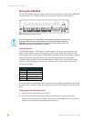
The 8-position DEVICE DIP switch sets the AXlink identification number for the AXB-CAM.
Make sure the device number matches the number assigned in the AXCESS software program.
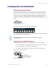
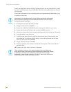
When you set the first device number on the
DEVICE DIP switch, the AXB-IRS4 automatically
assigns the next three device numbers. For example, if you set the
DEVICE DIP switch to 97
(1+32+64=97) as shown below, the AXB-IRS4 sets ports 1 through 4 as device numbers 97, 98, 99,
and 100.
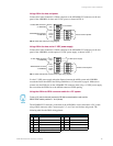
The following table describes the values on the
DEVICE DIP switch.
To reset the AXB-IRS4 with a new DIP switch device number, disconnect and connect the AXlink
or 12 VDC power connector on the AXB-IRS4.
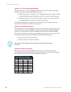
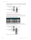
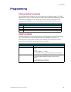
Setting the Carrier/BAUD DIP switch
The CARRIER/BAUD DIP switch sets the carrier signals and baud rates for the AXB-IRS4.
! DIP switch positions 1 through 4 set the carrier/NC signal option for ports 1 through 4.
! DIP switch position 5 is used for RS-232 or PCTouch mode.
! DIP switch positions 6 through 8 set the baud rate for RS-232 data communication.
FIG. 2 shows the DIP switch positions.
FIG. 1 DEVICE DIP switch, set to 97
Device DIP Switch Settings
Position 12345678
Value 1 2 4 8 16 32 64 128
1 2 3 4 5 6 7 8
ON
DEVICE
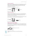
If the AXB-IRS4 is wired for RS-232 communication, set all eight DIP switch positions
to the off (up) position.
FIG. 2 CARRIER/BAUD DIP switch
CARRIER/BAUD
1 2 3 4 5 6 7 8
NC
Baud rate settings
RS232/PCTouch mode select
Carrier signal enable/disable