


Installation
4
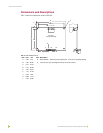
AXP-AI8 Eight-Channel Analog Interface Board
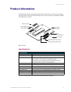
Wiring
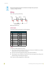
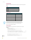
FIG. 4 shows typical joystick wiring:
20-Pin Header
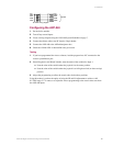
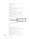
The following table lists the pinouts for the 20-pin header:
AXlink
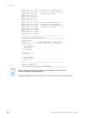
To install the AXlink data/power bus wiring:
1. Strip .25 inch off the wire insulation for all four wires. If the wire is 20 AWG or less, fold the
exposed wire over to obtain a positive connection.
2. Insert each wire into the appropriate opening on the connector. See FIG. 4.
3. Turn the captive screws clockwise to secure the fit. Do not over torque the screw; doing so can
bend the seating pin and damage the connector.
FIG. 5 shows the wiring configuration for AXlink cables.
Be sure that the board input ground is connected to the voltage source ground prior
to applying a voltage to the input.
FIG. 4 Typical joystick wiring
20-Pin Header - Pinout Information
Pin Function Pin Function
1GND 11GND
2 INPUT 1 12 INPUT 6
3GND 13GND
4 INPUT 2 14 INPUT 7
5GND 15GND
6 INPUT 3 16 INPUT 8
7GND 17GND
8 INPUT 4 18 GND
9 GND 19 +5 VDC REF
10 INPUT 5 20 +5 VDC REF
19,20
2
17,18
Pan
4 Tilt 6Zoom 8Focus
GND
+5V DC REF
+5 VDC REF 19,20
GND 17, 18
Pan 2 Zoom 6Tilt 4
Focus 8