


Installation
5
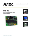
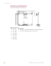
AXP-AI8 Eight-Channel Analog Interface Board
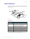
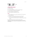
Configuring the AXP-AI8
1. Set the device number.
2. Turn off any unused inputs.
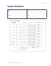
3. Create a wiring diagram using the AXP-AI8 System Worksheet on page 7.
4. Connect the ribbon cable or the PC board to 20-pin header.
5. Connect the AXP-AI8 to the AXlink data/power bus.
6. Check the AXlink LED. It should blink once per second.
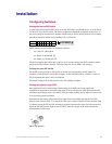
Testing
1. If you have programmed the Axcess software, load the program into a PC connected to the
control system Master port.
2. Select Diagnostics and Watch Variable; enter the name of the variable for Input 1.
Note the value of the variable when the joystick is in the center position.
Note the value of the variable when the joystick is at full right and left (or down and up)
position.
3. Adjust the programming to reflect the actual values for the three positions.
Using this method, you have the option of using the HI and LO adjustments to achieve a full
0-5 VDC range, 2.5 V center, or to adjust the Axcess programming to the actual values sent from
the AXP-AI8 inputs.
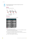
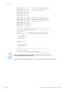
FIG. 5 AXlink wiring diagram
SYSTEM
GND
AXM
AXP
PWR
GND
AXM
AXP
PWR
PWR
AXP
AXM
GND
PWR
AXP
AXM
GND
System