


4
AXP-CPI16 16-Channel Custom Panel Interface
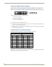
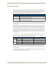
Setting the AXlink Device Number
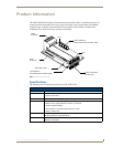
The 8-position device DIP switch defines the AXP-CPI16 as an AXlink device. It can be one of 255
devices in the Axcess Control System. Set the device number with the total value of all ON (down)
positions. As an example, the device DIP switch shown below defines device number 129 (1+128=129).
AMX standard device numbers are assigned as follows:
Cards are 1 through 25.
Boxes are 96 through 127.
Panels are 128 through 255.
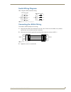
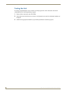
1. Strip 0.25 inch of wire insulation off all wires.
2. Insert each wire into the appropriate opening on the connector according to the wiring diagrams and
connector types described in this section.
3. Tighten the screws to secure the wires. Do not tighten the screws excessively; doing so may strip the
threads and damage the connector.
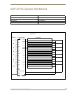
Connecting the Two 20-pin Headers
The following chart notes the pinouts of the two 20-pin headers for P2 and P3.
Pin 10 provides +12 VDC power from AXlink bus. Add 1K series resistors when using AXP-CPI16 with
LED indicators receiving 12 VDC power from Pin 10.
Position12345678
Value 1 2 4 8 16 32 64 128
AXP-CPI16 P2/P3 Pinouts
P2 P3
Pin Function Pin Function Pin Function Pin Function
1 Output 1 11 GND 1 Output 9 11 GND
2 Output 2 12 GND 2 Output 10 12 GND
3 Output 3 13 Input 1 3 Output 11 13 Input 9
4 Output 4 14 Input 2 4 Output 12 14 Input 10
5 Output 5 15 Input 3 5 Output 13 15 Input 11
6 Output 6 16 Input 4 6 Output 14 16 Input 12
7 Output 7 17 Input 5 7 Output 15 17 Input 13
8 Output 8 18 Input 6 8 Output 16 18 Input 14
9 GND 19 Input 7 9 GND 19 Input 15
10 PWR 20 Input 8 10 PWR 20 Input 16
1 2 3 4 5 6 7 8
ON
OFF
OFF
ON