


5
A
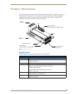
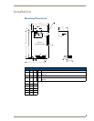
XP-CPI16 16-Channel Custom Panel Interface
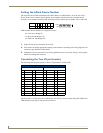
Switch Wiring Diagrams
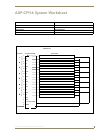
FIG. 2 diagrams LED and Switch wiring.
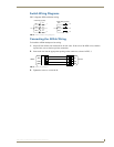
Connecting the AXlink Wiring
To install the AXlink data/power bus wiring.
1. Strip 0.25 inch off the wire insulation for all four wires. If the wire is 20 AWG or less, fold the
exposed wire over to obtain a positive connection.
2. Insert each wire into the appropriate opening on the connector, as shown in FIG. 3.
3. Tighten the screws to secure the fit.
FIG. 2 LED and switch wiring diagrams
FIG. 3 AXlink wiring diagram
3
LED 3
LED 2
10
LED 1
1
2
1K
1K
1K
LED Wiring (Typical)
SW 3
15
SW 1
SW 2
12
13
14
Switch Wiring (Typical)
PWR
AXP
AXM
GND
PWR
AXP
AXM
GND
AXlink Device