


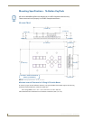

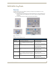
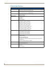

NOVARA AxLink KeyPads
22
Novara ControlPads & KeyPads
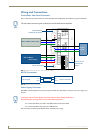
Wiring and Connections
ControlPads - Rear Panel Connectors
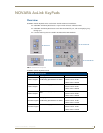
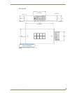
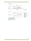
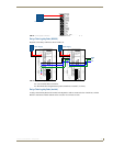
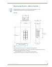
FIG. 7 shows the rear panel connectors of the NOVARA AxLink KeyPads, and indicates a typical installation:
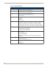
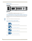
RS-232 Connections
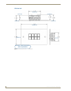
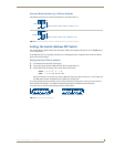
Power Supply Connector
NOVARA AxLink KeyPads can be powered by the AxLink bus. Optionally, an external 12V power supply can
be used.
Connect the White strip lead to the +VE terminal on the ControlPad
Connect the Black strip lead to the –VE terminal
FIG. 9 illustrates connecting the KeyPad to the included power supply.
The rear panel connector layout is identical for all NOVARA AxLink KeyPads.
FIG. 7 NOVARA AxLink KeyPads - Rear Panel Connectors
FIG. 8 RS232 Control - Connections
To other
Keypad
Alternate Button
Numbering DIP Switch
AxLink Device
Address DIP
AxLink Status LED
NetLinx Master (Serial port)
NetLinx Master
(AxLink port)
Switch
From KeyPad
RX
TX
Gnd
External Controller
Feedback
TX
RX
Gnd
If using an external Power Supply, be aware that the Power Supply polarities on
Novara KeyPads are opposite to that of other AMX equipment.