


2
Multigang Installations
In multigang installations, several controls are grouped hori-
zontally in one multigang wallbox.
• No derating is required for Remotes.
• When ganging Remotes with dimmers or switches in the
same wallbox, derating is required for the dimmers or
switches. See the installation instructions that came with
the dimmer or switch for derating requirements.
Note: Controls do not have fins that need to be removed for
multigang installations.
Installation
Short Circuit Check: Check the installation for short cir-
cuits before installing control(s). With power OFF, install
standard mechanical switch(es) between Hot and load.
Restore power. If lights do not work or a breaker trips,
check wiring. Correct wiring and check again. Install con-
trol(s) only when short is no longer present. Warranty is void
if control is turned ON with a shorted circuit.
Danger - Locate and remove fuse or lock circuit
breaker in the OFF position before proceeding.
Wiring with power ON may result in personal
injury.
1. Turn power OFF at fusebox or circuit breaker.
2. Prepare wires. When making wire connections, follow the
recommended strip lengths and combinations for the
supplied wire connectors. Note: Wire connectors provid-
ed are suitable for copper wire only.
Large:
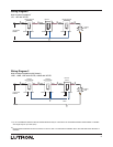
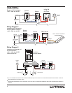
3. Wire controls using Wiring Diagrams 1 and 2 (page 3).
When using power boosters or interfaces, use Wiring
Diagrams 3, 4, and 5 (page 4). Up to nine HD-RD or HD-
RS remotes may be connected to the -6D, -6ND, -10D, -
10ND, -5NE, or -8ANS controls.
4. Push all wires back into the wallbox and loosely fasten
the control to the wallbox using the control mounting
screws provided. Do not pinch the wires.
Large
Strip insulation 1/2" (13mm) for #10 AWG
(6mm
2
), #12 AWG (4mm
2
) or #14 AWG
(2.5mm
2
).
Strip insulation 5/8" (16mm) for #16 AWG
(1.5mm
2
) or #18 AWG (1.0mm
2
).
Use to join one or two #12 or 14 AWG sup-
ply wires with one #10, 12, 14, 16 or 18
AWG control wire.
5. Attach Lutron Claro® or Satin ColorsTM wallplate adapter
and wallplate.
a. Loosely install control mounting screws.
b. Tighten wallplate adapter mounting screws snug.
c. Tighten control mounting screws until wallplate
adapter is flush to wall (do not over-tighten).
d. Snap wallplate onto wallplate adapter, and verify
that control is not submerged.
e. If control is submerged, loosen mounting screws
appropriately.
6. Complete wiring for all dimmers, switches and remotes in
this circuit.
7. Restore power. Check for correct local operation (see
Local Operation, page 5).
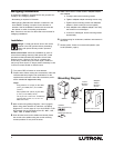
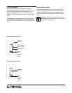
Mounting Diagram
Wallplate/Adapter purchased
separately.
Control
Mounting
Screws
Wallbox
Control
Included:
Wire Connectors (4)
Mounting Screws (2)
Wallplate
Adapter
Mounting
Screws