


Installation
4
PCS and PCS2 Power Current Sensors
Preparing captive wires
You will need a wire stripper and flat-blade screwdriver to prepare and connect the captive wires.
1. Strip 0.25 inch (6.35 mm) of insulation off all wires.
2. Insert each wire into the appropriate opening on the connector according to the wiring
diagrams and connector types described in this section.
3. Turn the flat-head screws clockwise to secure the wire in the connector. Do not over-torque the
screws; doing so can bend the seating pin and damage the connector.
PCS to AXC-INP8
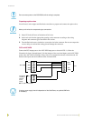
Connect the PCS output ports to the AXC-INP8 input ports as shown in FIG. 1; follow the
illustration for input 1 through input 8. Set the jumpers of the associated inputs on the AXC-INP8
(refer to the AXC-INP8 Switch/Opto Voltage Input Card instruction manual) to Switch mode. All
Switch mode inputs and the CardFrame share common GND.
Do not connect power to the PCS/PCS2 until the wiring is complete.
Never pre-tin wires for compression-type connections.
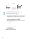
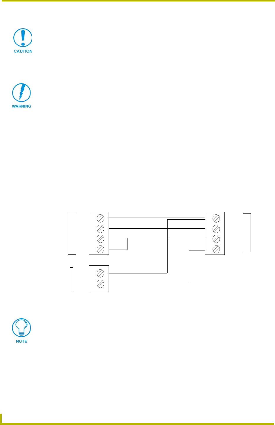
FIG. 1 PCS to AXC-INP8
PCS
GND
STBY
ON
PWR
INP1
INP2
GND (-)
+
CardFrame
12 VDC or
external
power
AXC-INP8
GND
GND
supply
If using a power supply that is independent of the CardFrame, an optional GND wire
is necessary.