


Installation
5
PCS and PCS2 Power Current Sensors
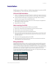
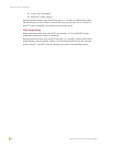
PCS2 to AXC-INP8
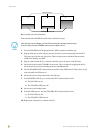
Connect the PCS2 output ports to the AXC-INP8 input ports, as illustrated in FIG. 2. Follow the
illustration for Input 1 through Input 8. Set the jumpers of the associated inputs on the AXC-INP8
to Switch mode. All Switch mode inputs and the Card-Frame share common GND.
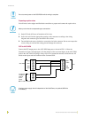
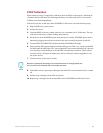
PCS to Axcent, Axcent
2
, or Axcent
3
Connect the PCS output and power ports to the Axcent, Axcent
2
, or Axcent
3
input/output (I/O)
ports, as illustrated in FIG. 3. Provide 12 VDC power from the Panja system power supply or an
external power supply.
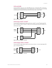
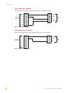
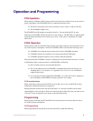
PCS2 to Axcent, Axcent
2
, or Axcent
3
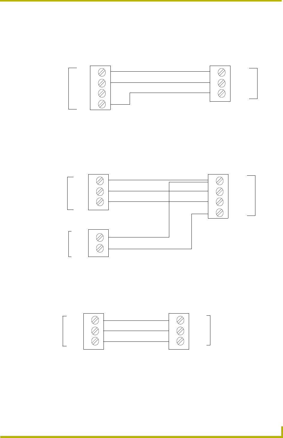
Connect the PCS2 output and power ports to the Axcent, Axcent
2
, or Axcent
3
input/output (I/O)
ports, as illustrated in FIG. 4.
FIG. 2 PCS2 to AXC-INP8
FIG. 3 PCS to Axcent, Axcent2, or Axcent3
FIG. 4 PCS to Axcent, Axcent2, or Axcent3
PCS2
COM
STBY
ON
INP1
INP2
AXC-INP8
GND
GND
PCS
GND
STBY
ON
PWR
I/O 1
GND (-)
+
Axcent
GND
I/O 2
Axcent
2
Axcent
3
12 VDC
COM
STBY
ON
GND
I/O 1
I/O 2
PCS2
Axcent
Axcent
2
Axcent
3