


BROAD SCAN (HD/SDI) APPENDIX A / ANNEXE A
PAGE 43
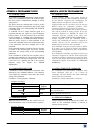
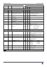
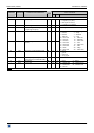
COMMAND RESPONSE COMMAND DESCRIPTION VALUE /VALEUR
COMMANDE RÉPONSE DESCRIPTION DE LA COMMANDE
TYPE
MIN MAX DESCRIPTION
STATUS COMMANDS / COMMANDES D’ETAT
IK IK Input sync type detection
Rd
0 3 0 = separate H & V
1 = Composite sync (TTL)
2 = SOG (Sync On Green)
3 = Composite sync (analog)
II II Interlaced signal detection.
Rd
0 1 0 = not interlaced 1 = interlaced
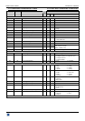
IO IO Status of the signal in comparison with
the input range frequency.
Rd
0 1 0 = in range 1 = out of range
IF IF Input format detection
Rd
0 25
XF XF Status of the synchronized format
(genlock).
Rd
0 25
0 = No signal 1= Wrong signal
4 = 640x480 5 = 480p
6 = 852x480 7 = 800x600
8 = 1280x720 9 = 720p
10 = 10274x768 11 = 1280x768
12 = 1366x768 13 = 1280x800
14 = 1280x960 15 = 1280x1024
16 = 1364x1024 17 = 1035i
18 = 1400x1050 19 = 1680x1050
20 = 1920x1080 21 = 1080i
22 = 1080sf 23 = 1080p
24 = 1600x1200 25 = 1920x1200
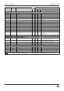
XA XA Status of the synchronization mode
Rd
0 3 0 = internal
1 = genlock
2 = frame lock
3 = wrong signal.
XT XT Frame frequency of the synchronized
signal (genlock) (in hundredth of Hz)
Rd
0 65535
CC CC Selected Input
Rd
1 2 1 = Source 2 = Frame
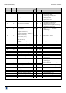
? DEV Device model
Rd
59 63 59 = BHD930-DG 60 = BHD930-AG
61 = BSD830-DG 62 = BSD830-AG
63 = BSC730
NOTE: Rd = Read only command / Commande de lecture. Rd/Wr = Read and write command / Commande de lecture et d'écriture.