


Evaluation Board User Guide UG-001
Rev. 0 | Page 11 of 24
0
7782-029
07782-030
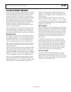
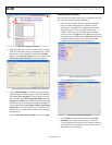
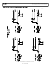
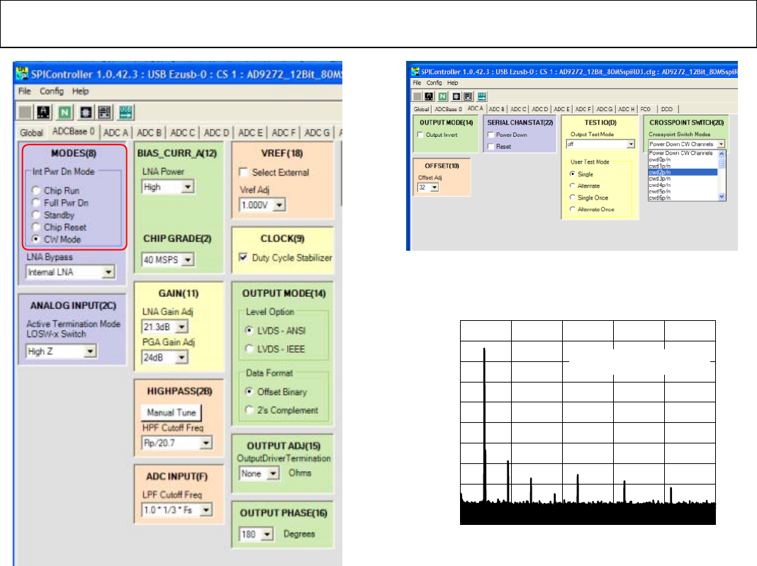
Figure 19. SPI Controller, CROSSPOINT SWITCH(2D) Box
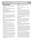
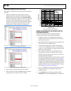
8. Examine the spectrum analyzer for the CW Doppler output
(see Figure 20 for an example).
0
–10
–20
–30
–40
–50
–60
–70
–80
–90
–100
02
07782-004
FREQUENCY (MHz)
AMPLITUDE (dBm)
51015205
FREQUENCY = 2.3MHz
CWD1±, DIFFERENTIAL OUTPUT
Figure 20. Typical Spectrum Analyzer Display of CWD Output
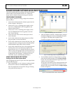
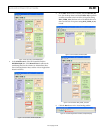
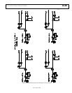
Figure 18. SPI Controller, MODES(8) Box
7. In the ADC x tab of the SPI Controller, where x is the channel
to which an analog input is applied, find the CROSSPOINT
SWITCH(2D) box. From the Crosspoint Switch Modes
drop-down box, select the cwd2p/n option (see Figure 19).