


Evaluation Board User Guide UG-002
Rev. 0 | Page 3 of 12
EVALUATION BOARD HARDWARE
The following instructions are for setting up the physical
connections to the AD9551 evaluation board.
SETTING UP THE POWER AND PC CONNECTIONS
Set up the power and PC connections as follows:
1. Install the AD9551 evaluation software before connecting
the evaluation board to your PC for the first time (see the
Installing the Software section). Administrative privileges
are required for installation.
The AD9551 has the option of either being pin or register
programmable. If the pin programmable option is desired,
then no software is needed to control the part. However, it
is recommended to install the software because if it is not
installed, the computer will recognize the evaluation board
as new hardware and attempt to install drivers.
2. Connect the USB cables to the evaluation board and the
computer.
The red LED labeled VBUS (CR2) on the AD9551 evaluation
board should illuminate, and the USBSTAT LED should start
blinking. If the USBSTAT LED is not blinking, ensure that
the USB port on the PC is operational and that the USB cable
is not damaged.
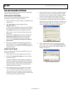
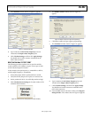
3. If the Found New Hardware Wizard automatically
appears when the evaluation board is connected, select
Install the software automatically and then click Next.
The Found New Hardware Wizard may appear twice, and
a system restart may be required.
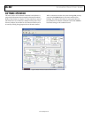
Refer to the
Evaluation Board Software section for details on
running the AD9551 evaluation board software.
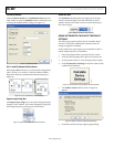
SETTING UP THE SIGNAL CONNECTIONS
After setting up the power and PC connections, use the
following procedure to set up the signal connections:
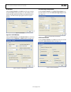
1. Connect a signal generator to REF A SMA Connector J1.
By default, the reference inputs on this evaluation board
are ac-coupled and terminated 50 to ground. An
amplitude setting of 6 dBm is sufficient.
2. To connect a signal to REF B, connect the signal to SMA
Connector J2.
3. Connect an oscilloscope, spectrum analyzer, or other lab
equipment to any of the J3 to J6 SMA connectors on the
upper right side of the board. The output connectors are
single ended. A 50 Ω termination should be placed on all
unused outputs.
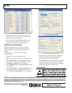
BYPASSING THE USB POWER SUPPLY
The evaluation board can be configured to supply power to the
AD9551 from an external power supply. Bypass the USB power
supply as follows:
1. Remove the F2 ferrite bead (located on the backside of
the board).
2. Connect a bench power supply to Pin 3.3V_1 of TB1 on
the evaluation board. In addition, resistors on the evaluation
board can be removed to further separate power supply
connections to the AD9551. This is useful for measuring
the AD9551 power consumption. Refer to the evaluation
board schematics provided on the CD in the evaluation board
kit (also available at www.analog.com) for further details.