


4. Lift your motherboard away from the standoff holes.
5. Screw the brass standoffs into the threaded holes that line up with your
motherboard. Do not overtighten the standoffs. Some standoffs may be
preinstalled for your convenience.
6. Place your motherboard on the brass standoffs.
7. Attach your motherboard to the standoffs with the provided Phillips-head
screws. Your motherboard is now installed.
Connecting the Power Switch and LEDs
1. Connect the 20-pin ATX power connector from your power supply (and
AUX or +12V connectors if appropriate) to your motherboard.
2. The Reset switch (labeled RESET SW) connects to your motherboard at the
RST connector. Make sure you always attach the colored wire to Pin 1,
and the black wire to ground.
3. Connect the Power Switch (labeled POWER SW) to the PWR connector on
the motherboard.
4. The Power LED, Hard Drive LED, and Speaker connectors all share a single
ribbon cable. Attach the POWER LED, HDD LED connector and SPEAKER
connectors to the appropriate headers on your motherboard.
Connecting the USB ports
There are two black 5-pin USB connectors on cables attached to the front
bezel. Here's how to connect them to your motherboard headers:
1. Check the USB pin layout in your motherboard's user manual and make
sure it follows this standard pinout:
Pin 1: USB Power - may also be labeled +5V
Pin 2: Negative Signal - may also be labeled P-, D-, USB0-, etc.
Pin 3: Positive Signal - may also be labeled P+, D+, USB0+, etc.
Pin 4: Ground
Pin 5: Ground
2. Plug the 5-pin USB connectors onto the header rows so that the RED wire
is on Pin 1 (Power, or +5V). The second header may be reversed (Power
pin at the opposite end of the row) so be careful when you plug in both
connectors.
Connecting the Audio Ports
There are seven individual wires and connectors coming from the front panel
for speaker and microphone. Attach them as follows:
1. Locate the internal audio connectors on your motherboard or sound card.
2. Consult your motherboard or sound card manual for the pin-out positions.
3. Connect the MIC connector to the microphone power pin.
4. Connect the MIC-BIAS connector to the microphone input pin.
5. Connect the AUD GND connector to the ground pin.
6. Connect the FPOUT-R connector to the Front Right Speaker Out Pin.
7. Connect the FPOUT-L connector to the Front Left Speaker Out Pin.
8. Connect the RET-R connector to the Rear Right Speaker Out Pin.
9. Connect the RET-L connector to the Rear Left Speaker Out Pin.
Note: If your motherboard doesn't support rear speaker output, you don't need
At Antec, we continually refine and improve our products to ensure the highest
quality. So it's possible that your new case may differ slightly from the descriptions
in this manual. This isn't a problem; it's simply an improvement. As of the date
of publication, all features, descriptions, and illustrations in this manual are correct.
Super LANBOY User's Manual
Anodized Aluminum Super Mini Tower Case
We don't include a power supply with the Super LANBOY. So you're free to
choose one that best suits your needs. Make sure you choose a PS/2 size power
supply that conforms to the ATX standard and is compatible with your mother-
board. Most systems conform to either the ATX12V or ATX2.03 standard.
Setting up
1. Take the case out of the box. Remove the Styrofoam and the plastic bag.
2. Place the case upright on a flat surface, with the rear of the case facing you.
3. Remove the thumbscrews from the right side panel. Open the case by
pulling the panel away from the case.
4. Inside the case, you'll see wiring with marked connectors (USB, PWR etc.),
an installed I/O panel and a power cord.
5. Swing the front panel open. You'll see a toolbox with a picture frame on it.
To open the toolbox, simply push on it. To lock it into position, push on it
again. Inside the toolbox, you can store hardware or small tools (screws,
brass standoffs, plastic stands, etc.)
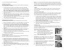
Installing the power supply
1. With the case upright, place the power supply in the top rear of the case.
Note: most dual-fan power supplies should be installed with the second fan
towards the bottom of the case.
2. Push the power supply to the back of the case and align the mounting holes.
3. Attach the power supply to the case, using the screws provided.
Installing the motherboard
This manual does not cover CPU, RAM, or expansion card installation. Please
consult your motherboard manual for specific mounting instructions and
troubleshooting.
1. Lay the case down, with the open side facing up. The drive cages should
be visible.
2. Make sure you have the correct I/O panel for your motherboard. If the
panel provided with the case isn't suitable, please contact your mother
board manufacturer for the correct I/O panel.
3. Line up your motherboard with the standoff holes, and remember which
holes are lined up. Not all motherboards will match with all of the provided
holes; this is normal, and won't affect functionality.
Disclaimer
This manual is intended only as a guide for Antec's Computer Enclosures. For more comprehensive
instructions on installing your motherboard and peripherals, please refer to the user's manuals which
come with your components and drives.
1
2