


3
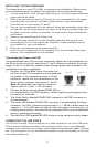
Motherboard Pin Layout
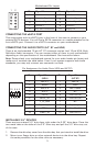
CONNECTING THE eSATA PORT
This case comes with an eSATA port in the front of the case to connect to your
external SATA devices. You will find a SATA connector on a cable attached to the
front eSATA port. Connect it to a SATA connector on your motherboard.
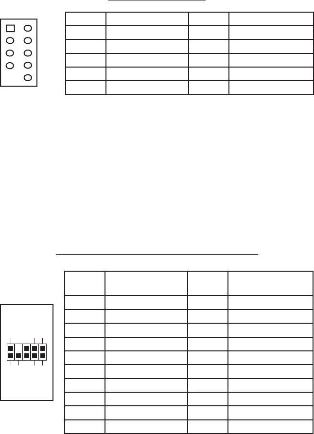
CONNECTING THE AUDIO PORTS (AC’ 97 and HDA)
There is an Intel standard 10-pin AC’ 97 connector and an Intel 10-pin HDA (High
Definition Audio) connector. You can connect either of them to your motherboard
depending on the specification of the motherboard. See instruction below:
Note: Please check your motherboard manual for your audio header pin layout and
make sure it matches the table below. Even if your system supports both audio
standards, you may only connect one connector not both.
Pin Assignment for Audio Ports (HDA and AC’97)
INSTALLING 3.5” DEVICES
There are two external 3.5” drive bays right under the 5.25” drive bays. Press the
two metal tabs on the sides of the 3.5” drive tray and pull the 3.5” drive tray out
of the case.
1. Remove the drive bay cover from the drive bay that you intend to install the drive.
2. Mount your floppy drive or other external device into the drive bay. Repeat
the same procedure for the other drive as necessary.
Pin Signal Names
(HDA)
Pin Signal Names
(AC’97)
1 MIC2 L 1 MIC In
2 AGND 2 GND
3 MIC2 R 3 MIC Power
4 AVCC 4 NC
5 FRO-R 5 Line Out (R)
6 MIC2_JD 6 Line Out (R)
7 F_IO_SEN 7 NC
8 Key (no pin) 8 Key (no pin)
9 FRO-L 9 Line Out (L)
10 LINE2_JD 10 Line Out (L)
1
2
3579
46
10
Pin Signal Names Pin Signal Names
1
USB Power 1
2
USB Power 2
3
Negative Signal 1
4
Negative Signal 2
5
Positive Signal 1
6
Positive Signal 2
7
Ground 1
8
Ground 2
9
Key (No Connection)
10
Empty Pin
12
109