


5
Setting Up
1. Place the case upright on a flat, stable surface.
2. Loosen the thumbscrews from the left side panel. Remove it by swinging it out. Note:
Don't use your fingernail to pry or lift the panels.
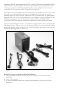
3. Inside the case you should see the power supply, some wiring with marked connectors (USB,
PWR etc.), an installed I/O panel, a power cord, a plastic bag containing modular PSU out
put cables, a toolbox with more hardware (screws, brass standoffs, plastic stands, etc.), and
six drive rails.
4. There are three plastic tabs on the left side of the bezel. They fasten the front bezel to the
metal chassis. Release the tabs from the top down to release the bezel.
5. Swing open the bezel to about a 45º angle and gently lift the bezel upward. The front bezel
will come off easily. Set the bezel in a safe place.
Installing the Motherboard
This manual does not cover CPU, RAM, or expansion card installation. Please consult your
motherboard manual for specific mounting instructions and troubleshooting.
1. Lay the case down, with the open side facing up. The drive cages and power supply should
be visible.
2. Make sure you have the correct I/O panel for your motherboard. If the panel provided with
the case isn't suitable, please contact your motherboard manufacturer for the correct I/O panel.
3. Line up your motherboard with the standoff holes, and remember which holes are lined up.
Not all motherboards will match with all the provided holes; this is normal, and won't affect
functionally. (In other words, there will likely be extra holes.)
4. Remove your motherboard by lifting it up.
5. Screw the brass standoffs into the threaded holes that line up with your motherboard. Do
not overtighten the standoffs. Some standoffs may be pre-installed for your convenience.
6. Place your motherboard on the brass standoffs.
7. Fasten your motherboard to the standoffs with the provided Philips-head screws. Your
motherboard is now installed.
Connecting the Front I/O
1. Connect the reset switch (labeled RESET SW) to your motherboard at the RST connector.
2. Connect the power LED (labeled POWER LED) to your motherboard.
3. Power switch (labeled POWER SW) connects to the PWR connector on the motherboard.
4. Connect the speaker (labeled SPEAKER) connector to the speaker connector on your
motherboard.
5. Hard drive LED (labeled H.D.D. LED) connects to the HDD connector on your
motherboard.
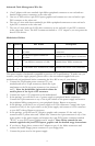
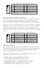
Connecting the USB Ports
You will find a single 10-pin connector on a cable attached to the front USB ports. This is an
Intel standard connector, which is keyed so that it can't be accidentally reversed as long as it is
connected to a proper Intel standard motherboard header. Connect the 10-pin connector to
your motherboard headers so that the blocked pin fits over the missing header pin.
Note: Please check your motherboard manual for your USB header pin layout and make sure it
matches the attached table. If it does not match this Intel standard, please call Antec customer
service at (800) 22ANTEC (North America) or +31 (0) 10 462-2060 (Europe) to buy a USB
adapter. This adapter will allow you to connect the front USB to your motherboard on a
pin-by-pin basis.